That's good to hear. I will make some tests anyway, comparing baked and non baked.with normaly mylar and thick enough alu it wont lose its corugation. if you go thinner then 7-10 micron it might though 🙁 i believe its also the ratio mylar+glue thickness vs thickness and softness of the alu. most alufoils i use in larger builds are 15micron , they hold shape fine
I think that I have what I need when it comes to the magnet system and the membrane.
At this stage anyway, I will for sure have more questions when I start to build.
But what about the Helmholtz resonance:

I want to push the Helmholtz resonator frequency up above 10 kHz, any potential harmonics will not be audible and the resonance itself might even be desireable helping the frequency response in the highs.
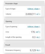
So the larger the opening area and the lesser cavity and opening depth will increane Helmholtz resonator frequency.

The cavity is in brown and the opening is in blue.
The cavity's area above is 211 mm2, so the volume is 2.2 m x 211 mm2 = 0.000464 m3 (0.464 litres).
Not taking the effective volume of the dampening itself into account.
The opening area is distributed across the front plate and has to be seen as a percentage of the area between the magnets.
The total opening area is 4 x 2.2 m x 5 mm = 0.044 m2 = 440 cm2.
With 40 % the opening area is 176 cm2.
The lenght of the opening area is 3 mm = 0.3 cm
I'm using this calculator.

Please correct me if I am wrong!
At this stage anyway, I will for sure have more questions when I start to build.
But what about the Helmholtz resonance:
I want to push the Helmholtz resonator frequency up above 10 kHz, any potential harmonics will not be audible and the resonance itself might even be desireable helping the frequency response in the highs.
So the larger the opening area and the lesser cavity and opening depth will increane Helmholtz resonator frequency.
The cavity is in brown and the opening is in blue.
The cavity's area above is 211 mm2, so the volume is 2.2 m x 211 mm2 = 0.000464 m3 (0.464 litres).
Not taking the effective volume of the dampening itself into account.
The opening area is distributed across the front plate and has to be seen as a percentage of the area between the magnets.
The total opening area is 4 x 2.2 m x 5 mm = 0.044 m2 = 440 cm2.
With 40 % the opening area is 176 cm2.
The lenght of the opening area is 3 mm = 0.3 cm
I'm using this calculator.
Please correct me if I am wrong!
Attachments
So if I can reduce the cavity volume to half and have a 2 mm thick steel plate I get:

And have a larger opening:

I don't know if that thin and perforated steel plate will hold the magnets in place.
And have a larger opening:
I don't know if that thin and perforated steel plate will hold the magnets in place.
Last edited:
So I changed the motor, having 100x5x3 mm magnets instead (Yes,l I know Joppe!). I also reduced the gap to 4 mm:

Giving an cavity area of 156 mm2 and thus a cavity volume of 0.0003432 m3.

With a more reasonable perforation ratio of 75% and 2mm steel plates, the Helmholtz resonator frequency is well above 10 kHz:

The reduced gap width compensate for the thinner magnets:

So the magnetic field density is still good:

The density's lineary is still very good:

Giving an cavity area of 156 mm2 and thus a cavity volume of 0.0003432 m3.
With a more reasonable perforation ratio of 75% and 2mm steel plates, the Helmholtz resonator frequency is well above 10 kHz:
The reduced gap width compensate for the thinner magnets:
So the magnetic field density is still good:
The density's lineary is still very good:
Attachments
nice !!! i never looked into that ! you get the 100x5x3 from itally ? they ahve rather good prices 🙂 i bought 1200 with a fellow member here 🙂
nice caculator you used to ! do you have a link, might come in handy in the future 🙂 2mm of steel is more then enough for a small driver, it depends on width of the steel and length of course... since B&G used 1.5-2mm in there push pull but there panels where not that big. and had ribs
Yes, hopefully I'll get them soon.
With a 1.5 mm steel plate,the Helmholtz resonator frequency is pushed up even further:

One might think that filling the space between the magnets and thus make a longer opening, will up the Helmholtz resonator frequency:

But alas, it is the other way around:

I'm using this calculator.
With a 1.5 mm steel plate,the Helmholtz resonator frequency is pushed up even further:
One might think that filling the space between the magnets and thus make a longer opening, will up the Helmholtz resonator frequency:
But alas, it is the other way around:
Thanks !! i noticed in one of my builds i used 8 mm gap (witch is large i know) but it looks rather smooth and use regular perf plate. witch so far worked better for me then the laser cut panels 🙁 then again im fine with 86 dB in single ended. since push push... becomes more of a thing below where i use them
PP or SE is not just about SPL.
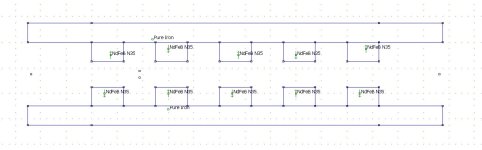
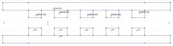
Here's a side by side comparison between PP (top) and SE (bottom):


Simulated magnetic field densities across the magnets were the membrane is:


The the tangential magnetic field intensities we use:


Almost half the intensity, as expected.
The normal magnetic field intensities we don't use and want as they will skew the membrane:


Almost zero for PP but a disaster for SE.
Simulated magnetic field intensities in the gap were the membrane moves, assuming we want an one millimeter Xmax:


Here we want the magnetic field intensity, normal as the simulation in 90 degrees here, to be linear as it will otherwise result in compression and other distortion:


That's less than 0.1 % for PP and 6 % for SE.
Here we don't want any tangential magnetic field intensity:


Six times higher for SE, but probably inaudible in both cases.
Now, Helmholtz resonator frequency can be easily equalized. It might even be inaudible if it is high enough.
But the distortion that single ended introduces cannot not be reduced with equalization.
Here's a side by side comparison between PP (top) and SE (bottom):
Simulated magnetic field densities across the magnets were the membrane is:
The the tangential magnetic field intensities we use:
Almost half the intensity, as expected.
The normal magnetic field intensities we don't use and want as they will skew the membrane:
Almost zero for PP but a disaster for SE.
Simulated magnetic field intensities in the gap were the membrane moves, assuming we want an one millimeter Xmax:
Here we want the magnetic field intensity, normal as the simulation in 90 degrees here, to be linear as it will otherwise result in compression and other distortion:
That's less than 0.1 % for PP and 6 % for SE.
Here we don't want any tangential magnetic field intensity:
Six times higher for SE, but probably inaudible in both cases.
Now, Helmholtz resonator frequency can be easily equalized. It might even be inaudible if it is high enough.
But the distortion that single ended introduces cannot not be reduced with equalization.
Attachments

nice one SE vs PP , there is some debate about calling it PP, depending what people mean by it 🙂 since it is not push pull.. hehe
but yeah that is a huge difference, and i still think it makes allot of sence down low. for tweeter duty on such a huge foil. (so things wont move at all) might not make a huge difference if any. but its cool to see in theory it does !! really nice project !!! i am glad you are buidling something like this 🙂 more people should !i did not know that graph could look so smooth in PP, i always had this garbage (single ended, like the picture before) so i never used it after that
but yeah that is a huge difference, and i still think it makes allot of sence down low. for tweeter duty on such a huge foil. (so things wont move at all) might not make a huge difference if any. but its cool to see in theory it does !! really nice project !!! i am glad you are buidling something like this 🙂 more people should !i did not know that graph could look so smooth in PP, i always had this garbage (single ended, like the picture before) so i never used it after that
there is one thing that people do forget. how smooth and flat a SE can measure due to not having any magnets in front , i personally think for top end it measures the best out of the gate without the need for DSP. depending on the length. since long ones need some sort of EQ anyways 🙂
Hi! There is many factors that you can change... Starting at this theoretical level is good and cost nothing. Next step is to do DOE.
Some experiments in a small scale.
Make a small prototype where you can change spacing, tension, foam density, and even a thin layer of textile as an air resistance (QUAD speakers) etc etc..
Measure max tension and min tension. Then try wide and narrow, long and short, smallest magnet and biggest magnet. With/without damping etc
Then you look on the parameters that you are most interested in.
Another way is to look on the "best in class" construction and make i better, and use DOE to make it better.
Yes, I will do DOE. The only things that are fixed is the size of the magnets and that it is a push-pull configuration.
And most probably the method of making the membrane.
And most probably the method of making the membrane.
Often commercial full range planar magnetic loudspeakers has in spite of their names still a ribbon tweeter.
I understand that it is hard to make one membrane that covers the full range, but why not a planar magnetic tweeter?
Anyway, here's my take on a planar magnetic push pull tweeter:


The gap is only 3 mm as the excursion doesn't need to be large for tweeter frequencies.
Dampening can be placed on the actual magnets.
Note that there's no steel plate between the magnets; it is almost a ribbon tweeter in that respect.
The downside is of course that the sound emitting area is only 5 mm wide and 220 cm long.
Helmholtz's resonator frequency is up:

If I have done the calculations correct, that is:

I don't know how much the tapered part of the steel affects the frequency.
So what do you reckon, is such a narrow tweeter feasible?
I understand that it is hard to make one membrane that covers the full range, but why not a planar magnetic tweeter?
Anyway, here's my take on a planar magnetic push pull tweeter:
The gap is only 3 mm as the excursion doesn't need to be large for tweeter frequencies.
Dampening can be placed on the actual magnets.
Note that there's no steel plate between the magnets; it is almost a ribbon tweeter in that respect.
The downside is of course that the sound emitting area is only 5 mm wide and 220 cm long.
Helmholtz's resonator frequency is up:
If I have done the calculations correct, that is:
I don't know how much the tapered part of the steel affects the frequency.
So what do you reckon, is such a narrow tweeter feasible?
yeah it is feasible, i made one in the past. problem is getting the current back down to feed it again. with a regular coil and 6 magnets the return patch adds to the output. but i am guessing you chose this on purpose 🙂 been extra small in width. i do like it, there is nothing in the way (metal or holes) will have rather great output, is small. only downer is the return path. either by wire (most efficient but needs soldering, or make gold plated fingers on pcb JLCPCB). or what i was thinking about on the same coil with very wide traces. something like this 🙂
The idea is that the left and right returns are not close to the magnet structure and are glued down on a spacer or something , so it can add to the output. getting impedance high enough becomes also harder without wasting to much power in the return path, thats why in this drawing they are much wider.

i still think having wires as return, is the most efficient (hardly any loss in the returns) , except that you want thick wire as return, and ripping the solder joint of the foil is rather easy 🙂 so maybe a kapton flex double sided piece with nice holes to solder in to could work miracles. tape it on the membrane where the connections are, solder it, then solder thick wires to the kapton flex pcb acting as a cable relief. i was thinking about this as well 🙂 for some time
The idea is that the left and right returns are not close to the magnet structure and are glued down on a spacer or something , so it can add to the output. getting impedance high enough becomes also harder without wasting to much power in the return path, thats why in this drawing they are much wider.
i still think having wires as return, is the most efficient (hardly any loss in the returns) , except that you want thick wire as return, and ripping the solder joint of the foil is rather easy 🙂 so maybe a kapton flex double sided piece with nice holes to solder in to could work miracles. tape it on the membrane where the connections are, solder it, then solder thick wires to the kapton flex pcb acting as a cable relief. i was thinking about this as well 🙂 for some time
Last edited:
Thank Wrinex for the valuable (as always) input.
I haven't thought of the return paths yet, but I think your suggestion with aluminium traces is the best; the return path can be made very wide as they can be folded before gluing them down.
Do you think that such a membrane really needs to be corrugated?
I haven't thought of the return paths yet, but I think your suggestion with aluminium traces is the best; the return path can be made very wide as they can be folded before gluing them down.
Do you think that such a membrane really needs to be corrugated?
- Home
- Loudspeakers
- Planars & Exotics
- Yet another Planar Magnetic Line Source, the SMAPPP