
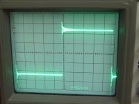
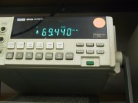
Here is the DC offset that I got from the amplifier. I didn't match any components on the board, as this was just an initial exercise to see if using SMD components.
Is this high for a Mini-A in terms of DC offset?
As for now, I am running this unit at 15v rails, and it draws approximately 1A from the power supply 😉 It is interesting to see a constant current draw, even without an input attached. I had previously only tested gainclones and leach amps on the setup, where the current draw varies with the input voltage.
--
Brian
Attachments
I have already gotten a couple of requests for pcbs 😀
I only made a couple of boards for this, stuffing the layout on some spare space on my CD-PRO2 prototype boards.
If there is enough interest, I do a board run. I didn't feel that enough people would want to do SMD boards, since it requires more patience to solder the boards, and there is less choice for exotic components.
Also, I can provide the gerber files if anyone wants to get their own boards made, or do a group order (not-for-profit, non-commerical use only)
Here is a picture of the layout for the pcb that I got made. You can see the Mini-A in the middle (2"x3" size)
--
Brian
Attachments
Brian,
Count me in for at least a half dozens sets of boards! Thats a really nice clean layout. I finished my Mini a while back and it had similar ringing. Try a .047 or thereabouts across the MPSA18 in the constant current source. That tok care of 95% of the ringing in mine...now just a slight overshoot. I'd be curious to hear from Nelson or Grey about what causes this ringing and overshoot. Its not audible as I couldn't hear any difference with or without the .047 in there. Miine is running both channels from a single 320 VA tranny at plus and minus 16 volts DC using a single 120,000 mfd Panasonic cap per rail.
A couple of weeks ago I tore my Mini apart to inboard the power supply which had been layiong next to it. I just finished up the extra work on the chassisc and got it running again tonight. This time I wired it up with 18 ga silver plated stranded OFC wire which made a HUGE difference in the high end and sound stage!!
Mark
Variac said:I wonder if Nelson's First Watt amps will be made like this?
I would doubt that... I am working on a version now, with through-hole components, and it will definately fit in the same package. I am also considering running a 2 pairs of parallel output devices instead, in a form factor 3"x3" (1" wider).
--
Brian
Member
Joined 2002
If you do so,
------------------------------------------------
I am also considering running a 2 pairs of parallel output devices instead
------------------------------------------------
it will not an "mini-A"
should be an "small-A"
😀
------------------------------------------------
I am also considering running a 2 pairs of parallel output devices instead
------------------------------------------------
it will not an "mini-A"
should be an "small-A"
😀
Forte said:If you do so,
------------------------------------------------
I am also considering running a 2 pairs of parallel output devices instead
------------------------------------------------
it will not an "mini-A"
should be an "small-A"
😀
4 devices essentially makes it an Aleph 5 - 30w amplifier...
(3d rendering from the board layout software)
--
Brian
Attachments
Neteagle said:What soft do you use to make your board ? It looks very nice !
Neteagle
Protel does 3D renderings... the main reason that I did the 3D rendering, is because I didn't finish routing all the traces yet.
--
Brian
- Status
- Not open for further replies.
- Home
- Amplifiers
- Pass Labs
- yet another Mini-A layout... (with SMD parts)