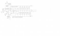
Thank you for respond.I am using this schematic.
https://drive.google.com/file/d/0B7kpRLNAmK8rdnBuSWF6VFBpcjQ/edit?usp=sharing
If you can't open this link let me know.
Actually I found in my board wrong capacitor C13,by pin#6 of lme49810.Should be 10pF,but I put 10nF.I didn't have time to put right one and check it.This weekend I will have time to show you my wave forms input and output with different frequency.
Actually I found in my board wrong capacitor C13,by pin#6 of lme49810.Should be 10pF,but I put 10nF.
That most certainly is the problem.
I scoped it. Not a thing . From 10hz to 100khz and the signal voltage was around 1-5 vrms. No output. Also tested the mute pin with an adj psu no change.
Zolux. Any progress?
Are you sure you have the C/E connected the right way on your output transistors?
If not that, I can not think anything else than a short on your PCB somewhere...
- Status
- This old topic is closed. If you want to reopen this topic, contact a moderator using the "Report Post" button.
- Home
- Amplifiers
- Chip Amps
- Yet another LM project (lme49810 + par CFP)