I'm having trouble coming up with a grounding scheme for my El Cheapo build. I've searched and read a lot, but I fail to see the bigger picture.
I've scrolled through the ppt and other documentation from hifisonix (thanks rayma), I've read Merlin Blencowe's chapter on grounding and read several threads. For my two guitar amps I've followed Blencowe very closely and that worked like a charm. Now with two channels, I don't know what to do...
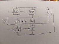
In order to get the discussion going I've got this image with the ground path in pink. Some ideas that are incorporated:
* Only one ground point at the input
* Ground loop has little area
* input references connected together (to ground)
* B+ and ground are twisted together.
Another idea would be to do it more like section 15.11 of http://www.valvewizard.co.uk/Grounding.pdf . That is a multichannel amp, not a stereo amp. So I guess we need to move the connection to ground to the 'non-audio grounds'.
Fire at will!
I've scrolled through the ppt and other documentation from hifisonix (thanks rayma), I've read Merlin Blencowe's chapter on grounding and read several threads. For my two guitar amps I've followed Blencowe very closely and that worked like a charm. Now with two channels, I don't know what to do...
In order to get the discussion going I've got this image with the ground path in pink. Some ideas that are incorporated:
* Only one ground point at the input
* Ground loop has little area
* input references connected together (to ground)
* B+ and ground are twisted together.
Another idea would be to do it more like section 15.11 of http://www.valvewizard.co.uk/Grounding.pdf . That is a multichannel amp, not a stereo amp. So I guess we need to move the connection to ground to the 'non-audio grounds'.
Fire at will!
Attachments

Last edited:
Tom, your image isn't very clear to me as to what you are trying to do. Perhaps a simplified circuit schematic sketch is better where the amp sections are 'boxes' but the ground point(s) are clearly shown with the parts going to those ground points, and the 0V distribution links are shown, and the connection(s) to chassis.
Thanks for your response. I will try to draw what you suggest, but it will have to wait until tomorrow. Now it's bed time.
If I understand your diagram it looks like you are making a bus for each channel based on you previous projects of mono amps, sorted very well it seems, and then turning this into a loop by connecting the 2 "big" current ends to each other, and the 2 "small" current ends to each other. If so, then no, you want to make 1 bus.
Last edited:
Yes, I'm making a bus per channel (as I did with single channel my guitar amps) based on Blencowes 'improved bus/multiple star' ground, grounded at the input (the 2 small current ends). And yes, I'm connecting both busses also at the power supply choke (the big current ends). I realised I had a ground loop, so I routed the grounds as indicated by the pink line in the image in the first post. That way the area of the ground loop is very small and magnetic induction will not be a problem.
What I realised as I read your post is that the second problem with ground loops still exists: Noise current may find an alternative return path.
Could someone explain to me how I make one bus in a stereo amp?
What I realised as I read your post is that the second problem with ground loops still exists: Noise current may find an alternative return path.
Could someone explain to me how I make one bus in a stereo amp?
Imagine the path generally as you have drawn it in pink, but instead of skipping over a nearby component that is on the other channel, connect your bus to it. If you try to imagine this, you will have 1 bus that runs generally like your pink loop does (you'll have to loop around a bit at the small signal end).
@leadbelly: So your suggestion is to simply 'collapse' my ground loop in post #7 to a single bus for both channels? That seems simple. But if it is that simple, why doesn't everyone do this? Isn't it a problem that (return) currents from one channel modulate the ground level of the other channel?
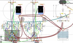
Surely the pink has a large 3D area - the loop from the suspended bus to the chassis also counts?
The main thing that stands out is for me - crossing signals and signals /ground at 90degrees?
The main thing that stands out is for me - crossing signals and signals /ground at 90degrees?
Sorry, can't help with existential questions. 😀
Grounding can be made to work in more than one way. Star grounds and intentional looping can be made to work.
IMHO the path of least resistance (pun intended) from your design to a working design is the single bus.
Grounding can be made to work in more than one way. Star grounds and intentional looping can be made to work.
IMHO the path of least resistance (pun intended) from your design to a working design is the single bus.
Well, at least in theory I can twist or shrink wrap most of the ground wires making the 3D area small. Don't know if the cure is worse that the decease though...
About the 90 degrees crossing. I get the reason, but can you pinpoint what stands out to you? Which crossings should be improved (once I figure out my grounding).
About the 90 degrees crossing. I get the reason, but can you pinpoint what stands out to you? Which crossings should be improved (once I figure out my grounding).
In the grounding sketch, what happens at the LTP end? Is the one earth symbol representing side-by-side input sockets grounding to chassis (either due to the sockets having metal cases, or due to the sockets being insulated from chassis, but the grounds at the location connecting to a single chassis point?
One approach is to move the single chassis connection link back to the last common point of the grounding scheme (ie use isolated input signal grounds). Another aspect is to supress external signals transferring via the signal inputs and the mains AC protective earth cable. At issue here is not just resistive connections both within and external due to input sources, but also the myriad stray capacitance paths/loop that can occur within an amplifier (ie. via capacitances in the power and output transformers to chassis), as well as loop area ingress from magnetic fields, and external radio frequency style signals coupling to high-input impedance input lines.
Likely the most accessible and understandable reference due to a focus on valve amps, and excellent descriptions and diagrams is Merlin's section on grounding. http://www.valvewizard.co.uk/Grounding.pdf
Last edited:
Yes, great pdf (I mentioned it in post #1) and the book and website are also wonderfull. I know it by heart (sorta...). It's a one stop shop for guitar amplifiers. However, it isn't that w.r.t. hifi amp for me.
Yes, exactly.
So option 2 from post #1. Move the ground point back to the choke, where the two channel split.
Can you pinpoint a case? I struggle to apply this generic statement to my amplifier (layout).
In the grounding sketch, what happens at the LTP end? Is the one earth symbol representing side-by-side input sockets grounding to chassis (either due to the sockets having metal cases, or due to the sockets being insulated from chassis, but the grounds at the location connecting to a single chassis point?
Yes, exactly.
One approach is to move the single chassis connection link back to the last common point of the grounding scheme (ie use isolated input signal grounds).
So option 2 from post #1. Move the ground point back to the choke, where the two channel split.
Another aspect is to supress external signals transferring via the signal inputs and the mains AC protective earth cable. At issue here is not just resistive connections both within and external due to input sources, but also the myriad stray capacitance paths/loop that can occur within an amplifier (ie. via capacitances in the power and output transformers to chassis), as well as loop area ingress from magnetic fields, and external radio frequency style signals coupling to high-input impedance input lines.
Can you pinpoint a case? I struggle to apply this generic statement to my amplifier (layout).
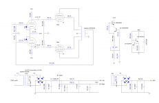
Can you be more specific about 'back to the choke', as there is no detailed schematic in this thread, and channel powering doesn't normally split 'at a choke'. Also any comments on layout require a good understanding of what you have or propose (ie. a schematic and the layout diagram marked up with key parts, given this amp hasn't progressed to operation yet).
Getting beyond Merlin's discussion, and introducing other noise ingress paths, is likely very dependant on the actual hardware and layout you have in place, and the external signal sources you are using, and whether this relates to a tangible noise or hum issue (ie. you can hear something, or you are chasing a certain SNR and have the equipment and setup to make measurements).
At this stage, given you are preparing what appears to be a guitar amp, I'd just go with a simple single 0V link to chassis from the most downstream common point, and use isolated input sockets, and then test.
It's no guitar amp. It's a European, not so cheap, El Cheapo.
I'm coming from guitar amps (2), that may show through.
I'm coming from guitar amps (2), that may show through.

Load current from one channel will also use the bulk capacitor from the other channel unless you include some L or R series component, if better channel separation is an aim. At the moment C6 and C13 are somewhat equally the last common 0V node, and perhaps simplest to use that 0V node as link to chassis, and to use insulated input sockets.
If this is for hi-fi, then what test equipment do you have and how low a noise floor do you want to achieve and can you test for that?
Preferably your schematic should unambiguously show where the 0V to chassis link is connected, as well as where other ground connections star to.
Are you going to include separate biasing for each output stage valve, as well as a dynamic gain adjust? Tube rolling and setting bias and gain are likely going to be the best method to minimise distortion (and hum given that you have feedback).
Do the valves use heaters?
Post #7 in this thread might answer the question (except for the highly questionable break resistor)
Load current from one channel will also use the bulk capacitor from the other channel unless you include some L or R series component, if better channel separation is an aim.
I agree. I think 220uF was not available at my supplier and came up with this idea.
At the moment C6 and C13 are somewhat equally the last common 0V node, and perhaps simplest to use that 0V node as link to chassis, and to use insulated input sockets.
So basically the second idea from post #1.
If this is for hi-fi, then what test equipment do you have and how low a noise floor do you want to achieve and can you test for that?
It is for hifi. I have an old scope and bought components for a (stereo) load. I'm still researching what would be the best option for further gear (leaning to agilent analog discovery like solution). Inaudible noise is enough. I'm used to (high gain) guitar amps. 🙂
Preferably your schematic should unambiguously show where the 0V to chassis link is connected, as well as where other ground connections star to.
I would like to do that on the layout and thats the reason I started this thread.
Are you going to include separate biasing for each output stage valve, as well as a dynamic gain adjust? Tube rolling and setting bias and gain are likely going to be the best method to minimise distortion (and hum given that you have feedback).
Every output valve has its own CCS biasing it. Don't know what you mean by dynamic gain adjust. Tube rolling and the like will have to wait. I'm trying to first get a decent starting point.
Do the valves use heaters?
Yes, the twisted blue/green heater wire layout is a starting point. Might change if needed. But for this thread let's focus on grounding.
Last edited:
- Home
- Amplifiers
- Tubes / Valves
- Yet another grounding thread