Yet another funny Chip-Amp: The Deviant
Hi there,
I have already described a number of amplifiers based on chips not initially intended for audio, mainly voltage regulators:
http://www.diyaudio.com/forums/chip-amps/176052-now-regulator-chip-jlh-amp.html
http://www.diyaudio.com/forums/chip-amps/192934-se-class-regulator-chip-amp-madness.html
http://www.diyaudio.com/forums/chip...oss-tringlotron-regulator-chip-amplifier.html
http://www.diyaudio.com/forums/chip-amps/193214-class-chip-amp-now-complementary-version.html
http://www.diyaudio.com/forums/chip...ator-chip-amp-family-welcomes-new-member.html
http://www.diyaudio.com/forums/chip-amps/175457-just-fun-regulator-chip-amplifier.html
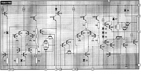
This time, I set my sights on another category of circuits, vertical deflection chips for CRT TV's.
These circuits contain a number of function blocks, including a power amplifier.
In its normal application, it is rather far off from an audio amplifier, being current output and featuring flyback handling circuitry, but it can very easily be converted to an audio amplifier.
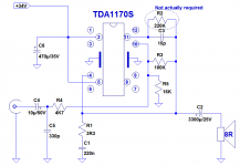
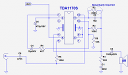
To that end, the flyback generator is left apart, and the PA supply is directly connected to the power supply.
The inverting input is available at pin 10, and is connected to the feedback divider formed by R3 and R4.
The DC output level is set by R5.
There is a compensation cap, C3 connected to an intermediate stage of the amplifier. There is also a 220K resistor, but it does seem to be useful for audio; it probably helps control the circuit during the flyback period, and its only apparent effect is to reduce the loop gain.
The inverting configuration is slightly inconvenient, because of the lowish input impedance, and the fact that the amp goes into unity gain when the source happens to be disconnected.
To avoid instabilities in this scenario, C5 provides an HF path to the ground.
Note that the feedback resistors could be made significantly larger without problem: the typical input bias current is only 100nA.
Now, the $1,000 question: does it actually work?
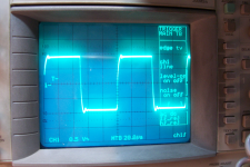
Yes!!!!, and rather well: it provides a good clean output, is well behaved even with a 10KHz squarewave and has a power bandwidth extending to 25KHz, quite OK for audio.
With a 34V supply, the output power reaches 13W at the onset of clipping.
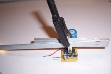
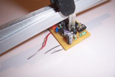
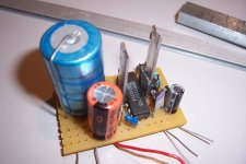
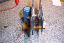
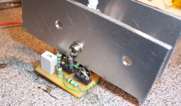
To cope with this power, I have improved on the original heatsinking method: I have made a U-shape copper heatsink link by bending a power bus strip.
It is soldered to the tabs, very close to the case to minimize the thermal resistance, and the underside is pressed against the bottom of the IC, with thermal compound in-between.
In those conditions, the chip has no problem delivering 13W sinus into 8Ω. It wouldn't be prudent to go lower, as the maximum peak current is already exceeded.
Could other function blocks be reused in an audio context?
The oscillator is probably ruled out, because of the positive feedback.
It would be tempting to use the flyback circuit to boost the supply voltage, like in Philips chips, but bits are missing, and it requires an inductive load to operate.
The internal regulator (pin 7) can be used to supply other circuits, like a preamp or a tone control.
The buffer, between 12 and 1 is probably perfectly usable, I will certainly try it.
One thing to be noted: this circuit does not include a short-circuit protection, and I had the occasion to verify it the hard way: an alligator clip went loose, brushed very shortly on something else, and it was gone.
Funny thing, it didn't go dead short, unlike 99.9% of semiconductors: instead, it went open circuit, something must have played the role of a fuse, either a bonding wire or a metallization.
This means that I didn't have time to carry out more detailed measurements, like THD for example, but anyway, it looked quite decent.
In short, a good little chip-amp requiring very little passive components and working surprisingly well.
Note that the TDA1170 is a very old circuit, modern IC's can certainly do better regarding power, bandwidth, and features like short-circuit or thermal protection
Hi there,
I have already described a number of amplifiers based on chips not initially intended for audio, mainly voltage regulators:
http://www.diyaudio.com/forums/chip-amps/176052-now-regulator-chip-jlh-amp.html
http://www.diyaudio.com/forums/chip-amps/192934-se-class-regulator-chip-amp-madness.html
http://www.diyaudio.com/forums/chip...oss-tringlotron-regulator-chip-amplifier.html
http://www.diyaudio.com/forums/chip-amps/193214-class-chip-amp-now-complementary-version.html
http://www.diyaudio.com/forums/chip...ator-chip-amp-family-welcomes-new-member.html
http://www.diyaudio.com/forums/chip-amps/175457-just-fun-regulator-chip-amplifier.html
This time, I set my sights on another category of circuits, vertical deflection chips for CRT TV's.
These circuits contain a number of function blocks, including a power amplifier.
In its normal application, it is rather far off from an audio amplifier, being current output and featuring flyback handling circuitry, but it can very easily be converted to an audio amplifier.
To that end, the flyback generator is left apart, and the PA supply is directly connected to the power supply.
The inverting input is available at pin 10, and is connected to the feedback divider formed by R3 and R4.
The DC output level is set by R5.
There is a compensation cap, C3 connected to an intermediate stage of the amplifier. There is also a 220K resistor, but it does seem to be useful for audio; it probably helps control the circuit during the flyback period, and its only apparent effect is to reduce the loop gain.
The inverting configuration is slightly inconvenient, because of the lowish input impedance, and the fact that the amp goes into unity gain when the source happens to be disconnected.
To avoid instabilities in this scenario, C5 provides an HF path to the ground.
Note that the feedback resistors could be made significantly larger without problem: the typical input bias current is only 100nA.
Now, the $1,000 question: does it actually work?
Yes!!!!, and rather well: it provides a good clean output, is well behaved even with a 10KHz squarewave and has a power bandwidth extending to 25KHz, quite OK for audio.
With a 34V supply, the output power reaches 13W at the onset of clipping.
To cope with this power, I have improved on the original heatsinking method: I have made a U-shape copper heatsink link by bending a power bus strip.
It is soldered to the tabs, very close to the case to minimize the thermal resistance, and the underside is pressed against the bottom of the IC, with thermal compound in-between.
In those conditions, the chip has no problem delivering 13W sinus into 8Ω. It wouldn't be prudent to go lower, as the maximum peak current is already exceeded.
Could other function blocks be reused in an audio context?
The oscillator is probably ruled out, because of the positive feedback.
It would be tempting to use the flyback circuit to boost the supply voltage, like in Philips chips, but bits are missing, and it requires an inductive load to operate.
The internal regulator (pin 7) can be used to supply other circuits, like a preamp or a tone control.
The buffer, between 12 and 1 is probably perfectly usable, I will certainly try it.
One thing to be noted: this circuit does not include a short-circuit protection, and I had the occasion to verify it the hard way: an alligator clip went loose, brushed very shortly on something else, and it was gone.
Funny thing, it didn't go dead short, unlike 99.9% of semiconductors: instead, it went open circuit, something must have played the role of a fuse, either a bonding wire or a metallization.
This means that I didn't have time to carry out more detailed measurements, like THD for example, but anyway, it looked quite decent.
In short, a good little chip-amp requiring very little passive components and working surprisingly well.
Note that the TDA1170 is a very old circuit, modern IC's can certainly do better regarding power, bandwidth, and features like short-circuit or thermal protection
Attachments
Last edited:

What's your view on the TDA4863AJ - another vertical deflection chip? Could that also work as an audio chipamp? Those are absurdly cheap on Taobao - about 15 for $1.
Yes, it should work. Plus points are differential inputs, like an ordinary amplifier, easier heatsinking, and thermal protection.What's your view on the TDA4863AJ - another vertical deflection chip? Could that also work as an audio chipamp? Those are absurdly cheap on Taobao - about 15 for $1.
On the negative side, the power won't be higher, the opposite in fact: the output current is only 1.8A.
Maybe you could draw more, but there's always a risk
I have replaced the fried TDA, installed a less flimsy heatsink arrangement, made some measurements, and tested the buffer option.
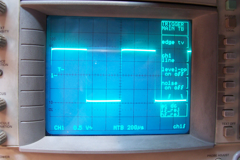
The THD @1KHz & 0.9 Pmax is 0.25%. Not super-low, of course, but still relatively decent.
For the square-wave response, see below: first 1KHz, then 10KHz.
Not marvelous, but also decent enough: probably better than some highly regarded tube amps for example.
The buffer does work, but it has issues: at first, I had connected pins 6 and 7, to make sure Q16 wouldn't interfere with the bias of the buffer, but nothing worked.
In fact, connecting pin 7 had the opposite effect than what could be inferred from the equivalent schematic: it pulled pin 12 almost to the + rail, and paralyzed the circuit.
In the end, I figured out that 7 should best be left floating.
Under those conditions, the buffer and the whole amplifier were working normally (I made the THD measurement with it), but the squarewave response had some ringing.
Probably some parasitic coupling or bypassing problem.
Note that no attempt was made to optimize the compensation, or to include a phase advance cap across the feedback resistor. Better results are certainly attainable with a bit more care
Edit
There has been a glitch in the uploading of the pics, and everything ended in a mix up, but the pics themselves are telling enough, I think there is no need for more explanations
Attachments

Last edited:
These circuits also offer additional possibilities: since the PA supply always has a dedicated pin (because of the flyback circuit), it is possible to use a higher supply for the power amp (the general supply voltage is limited to 35V, but the PA withstands 60V)
This feature can be used to boost the output power. Doing this on a 8Ω load would probably be unwise though, as the peak current would massively be exceeded, but on a higher impedance this should be possible: the current increases in direct proportion with the voltage, but power increases as V².
On a 16Ω load, and with a 60V supply, a power in excess of 24W should be reachable (heat evacuation could become a problem though)
That is doing something important, so long as you wanted nicely intelligible movies. That pattern is acutance.
The benefit is clarity. The cost is more effort with both the decoupling and also impedance matching attention (appropriate current drive) at the input.
When chip amplifiers can't give you exactly what you needed, then, in that case, the most probable culprit is that the power voltage is too high.
The benefit is clarity. The cost is more effort with both the decoupling and also impedance matching attention (appropriate current drive) at the input.
When chip amplifiers can't give you exactly what you needed, then, in that case, the most probable culprit is that the power voltage is too high.
Yet another example of diverted 317 use:
https://www.diyaudio.com/community/...m317-efficient-and-simple.402477/post-7432268
The role is minimal, as a CCS, but it qualifies
https://www.diyaudio.com/community/...m317-efficient-and-simple.402477/post-7432268
The role is minimal, as a CCS, but it qualifies
H
HAYK
The LM317 is not a dummy CCS here, the circuit is an SRPP. The current from the MOSFET modulates inversely the current of the lm317 which could be better with its 5A version, 338.
It can be done easily with another MOSFET as this.
Post in thread 'Single supply Low Power MOSFET Class A/AB amp' https://www.diyaudio.com/community/...wer-mosfet-class-a-ab-amp.403993/post-7475897
It can be done easily with another MOSFET as this.
Post in thread 'Single supply Low Power MOSFET Class A/AB amp' https://www.diyaudio.com/community/...wer-mosfet-class-a-ab-amp.403993/post-7475897
Last edited by a moderator:
Heh. That certainly would give the LM386 a run for the money. It'd be interesting to see what the THD is like.
Tom
Tom
Yet another example of diverted 317 use:
https://www.diyaudio.com/community/...m317-efficient-and-simple.402477/post-7432268
The role is minimal, as a CCS, but it qualifies
The virtue of the LM317 placed where I placed it is based on two concepts: increasing efficiency compared to a conventional CCS and maintaining static parameters more stable compared to other known options. Both concepts are achieved with a lot of circuit simplification (less components => less possibilities of failures or errors when building it). It is true that 3 or even 5A options could be used. Another possibility is to arrange several LM3XXs in parallel with great simplicity. Despite my initial doubts about the frequency response, I must admit that I was very pleasantly surprised by the extent of its response (at least with the manufacturer I built and tested it with).
The static current is only half of that needed in a single ended loaded with conventional CCS.
H
HAYK
Diego, the IRFZ44 is identical to IRFP150 but 60v, for a fraction of the cost.
- Home
- Amplifiers
- Chip Amps
- Yet another funny Chip-Amp