OK just ordered the psu stuff.
Still waiting the quote from Antek about the heatsinks + transformers + shields.
I hate this waiting part...
Still waiting the quote from Antek about the heatsinks + transformers + shields.
I hate this waiting part...
Just received the quote from Antek/Parmetal... Unfortunately the shipping cost is outrageous... And not taking into account the import custom fees...
I think I will go the HIFI2000 route if I don t manage to find any heatsinks here in Athens...
I think I will go the HIFI2000 route if I don t manage to find any heatsinks here in Athens...
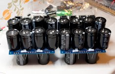
Just received the PSU caps. LOVE THE BIG CAPS 🙂
Perhaps next time I will get some of those huge cornel dublier ones and just keep it on my desk for decoration 😀
Unfortunately what slipped my atttention is that the 22kuF ones are 35mm and do not fit side by side on the board...
Fortunately the 33kuF ones are more than enough for a "textbook" build. I think I will stick to 4 of them for now (on the bottom of the boards, leaving the 8 top slots ready to receive the proper 22kuF ones), complete the "stock" circuit and then start changing/adding stuff.
Also got some CL30, CL60 and CL90 for experimenting, some FEP30DPs and heatsinks for the rectifiers and panasonic/vishay resistors for the rest of the psu parts.
I will hopefully finish the two boards today and post some porn for you 🙂
no experimenting with paralleled NTCs.............got some CL30, CL60 and CL90 for experimenting............
@Andrew
OK 🙂
I just got back from the cinema (OMG WANT MORE PROMITHEUS) and I m too tired to work on it now.
But I got some photos from the solderless rehersal which should be close enough 🙂
Apart from the 35mm 22kuF caps, I also forgot the 1/4w led ones. Which is no big deal since their value is not critical at all. I will use some 25k ones I already had.
Also the ohmite heatsinks for the diodes proved difficult to work with. The securing wire is stiff and you have to push them hard to fit. Really I see no reason why someone would want them rather than the ones with the screw/holes.
So here is one without the top caps

And here is one with the 35mm ones on top

Again, the most awkward part would be securing the boards on the chasis. It s going to need some looooooooong spacers
OK 🙂
I just got back from the cinema (OMG WANT MORE PROMITHEUS) and I m too tired to work on it now.
But I got some photos from the solderless rehersal which should be close enough 🙂
Apart from the 35mm 22kuF caps, I also forgot the 1/4w led ones. Which is no big deal since their value is not critical at all. I will use some 25k ones I already had.
Also the ohmite heatsinks for the diodes proved difficult to work with. The securing wire is stiff and you have to push them hard to fit. Really I see no reason why someone would want them rather than the ones with the screw/holes.
So here is one without the top caps
And here is one with the 35mm ones on top
Again, the most awkward part would be securing the boards on the chasis. It s going to need some looooooooong spacers
Attachments
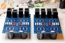
Just finished soldering the first psu board.
Here comes a small review of it. Nice one overall. I do not regret getting 4 of them. But I have to say that they have some design limitations.
First, with diode heatsinks in place, the space available for the jumpers (from rectifier to CRC part) is really tight. So tight that in case the jumper insulation wears off, there could be a short. I will try to fix this by soldering the jumper as close to the board as possible, and lifting the heatsinks as high as possible from it.
This reduces some mechanical strength on the rectifier part, but I don t think it will be a problem, as long as the diodes are not bent accidentally and the heatsinks do not touch each other... It is getting weird though... too many conditions.
I should use isolation pads on them. Or some mechanical spacer below the heatsinks to prevent the diodes from bending.
Second, the soldering pads for the 3W resistors are very thin. This makes them difficult to heat (I use an Ersa station with a 3mm chisel tip @450 celcius) especially on the center of the board where the plain is huge. And it is very easy to overdo it with solder (trying to get some flux and solder there) creating blobs on the wire and further making it difficult to see if the solder has properly flown on the pad. Pre-cutting the wires makes it a bit easier, but again it can get messy easily.
Third, my idea of soldering caps on both sides is a bit tricky with 30 and 35mm caps. With the caps tightly soldered close to the board, the pads of the other side caps are way too close to the cap of this side. So soldering the other side might destroy the center capacitor. I will try to get some spacers there to give the pads some air to breath.
And something minor. The led marking is really vague, so you have to go around the board a bit to figure out which way to solder them.
Anyway, it s a nice board and again I do not regret buying them.
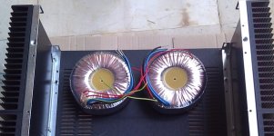
The transformers are flying over the Atlantic. I hope I' ll have them before the weekend (really doubt it though...)
I think I also decided to use the 4U 400mm pessante dissipante from HIFI2000 in black. The price is right. I just have to decide on the final layout and work on the faceplate design.
I think I also decided to use the 4U 400mm pessante dissipante from HIFI2000 in black. The price is right. I just have to decide on the final layout and work on the faceplate design.
The transformers are flying over the Atlantic. .......
are they gonna be cryo-threated ?

you don't have local supplier for xformers ?
I'm not finding those transantlantic xformers better than thisantlantic ones

Yeah I specifically asked that the pilot hangs the package from the wings during the flight so that they are cryoed. And since the altitude is going to be BIG, the result will be extremely HIGH-end. 😛
Well I have asked around and did not receive very good input on the local toroid ones. The EI are considered good, but I really don t like the idea of having separate PSU units. I usually like the Hammond ones (from mouser), but unfortunately they do not have big ones with 18V secondaries.
I was considering some French or Polish ones I was told about, but decided to get the Antek ones after all.
yup , I also heard that toroidi.pl are good
luckily , I have toroid xformer winder 25km from my place
dead silent in A class amps , what's most important , as proof of overall quality
luckily , I have toroid xformer winder 25km from my place
dead silent in A class amps , what's most important , as proof of overall quality
Serbia huh 🙂 I was playign warcraft with some guys from there and kept good relations with them till today 🙂 I might ask them to have a look at it 🙂
I was considering some French or Polish ones I was told about, but decided to get the Antek ones after all.
The polish are pretty good actually. I'm using two of them in my own build.
Last edited:
You guys mean toroidy.pl right?
I really hate it when there is no on-line catalogue 😛
That's the one! 😉
By the way, the photo above does not work.
Sorry mate...
Attachments
The polish are pretty good actually. I'm using two of them in my own build.
Price for them ? Including shipping?
Price for them ? Including shipping?
75 euros each shipping included. But it's been a while now...
- Status
- Not open for further replies.
- Home
- Amplifiers
- Pass Labs
- Yet another F5 building log