Hi everybody, there goes my first post.
Could you help me try to improve this little thingy.
I assembled it out of two old turntables and been using it for few years. There was some hum with the volume and tone control so I removed it altogether. When I found scheme and put them back in they made strange noise when operated. There are two power transformers, is it ok that they share common ground, could that be the culprit? Without pots everything is fine, but the sound is deficient from mids to highs, sounds a bit dark or muddy or dull. Since they were turntable amps, is there a RIAA eq curve implemented? I'm kind of strugling to grasp any amplifier topology, that's why I made that out of scheme, hope you won't freak out 🙂
Any help is much appreciated!
Look at the schematic on the last post on this thread the filament leeds have two 100 ohm resistors in series across them and a leed from the center of them going to the cathode of the output tube. This is a fairly common thing to do to cut down on hum. On your amp you would need to remove the ground connection from the filament transformer leed.
half polished turd, 6aq5 SE hummmmmm | Page 2 | Audiokarma Home Audio Stereo Discussion Forums
more info here on the elevated heater part. I would use 220 ohm resistors The Valve Wizard
half polished turd, 6aq5 SE hummmmmm | Page 2 | Audiokarma Home Audio Stereo Discussion Forums
more info here on the elevated heater part. I would use 220 ohm resistors The Valve Wizard
Last edited:
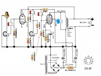
Those 22nF cap and 1M pot form a tone control. Today mostly seen in guitar amps.
I would take it out entirely.
Also that 4.7nF cap across the OT primary is there to dampen the high frequencies, to remove unwanted high frequency oscillations. Also possibly the speaker system could not handle proper highs, so they were filtered out this way.
4.7nF will most certainly cut out a lot of highs in the music frequencies as well. This kind of arrangement is mostly seen in guitar amps these days, to smoothen the sound.
I'd remove it, or try different values like 1nF or more likely 470pF or so.
Thank you all for help!
Ketje, You knew resistor value was wrong just by looking at the scheme? Wow!
I did everything but the elevated heaters. Don't know if I got it right, is 500k trim pot all that is needed, like in the new scheme?
The sound is very nice 🙂
Can I remove 4,7n and 10M and just put 220R between pot and triode gate?
(I'm improvising)
I'm also considering optocouplers for volume control, don't know if it's worth it, seems a bit complicated although that was simplest design I found...
Attachments
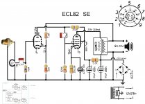
To get rid of those components you can do it like this.Can I remove 4,7n and 10M and just put 220R between pot and triode gate?
I'm also considering optocouplers for volume control, don't know if it's worth it, seems a bit complicated although that was simplest design I found...
The volume control looks complicated,is not, supply not fully drawn.As long as you have a decent 2,5V supply it's ok.
Talking about supplys, the one in the amp is not very good.Doesn't it have a lot of hum ?
Mona
Attachments
look at the two diagrams to the right of the elevating paragraphs on the valve wizard site its the lower of the two. You just need two resistors and connect the center of them to pin 2 of the tube and be sure you disconnect the filament wire from ground .If it's a circuit board you will need to cut the traces and use wires to connect to the tube.
Last edited:
I would increase the value of the two 50uF 400V smoothing caps to something like 220uF each. This will significantly reduce one source of hum.
Cheers
Ian
Cheers
Ian
Thanks to Mona I did changes to left channel for comparison, yes, sharper, clearer, more happier. Hum is also more present, or less damped, but anyways hum gets inaudible only one foot from the speaker (better than any amp I had so far).
Kenben I finally got what you ment, that capacitor and resistor with no value confused me, but they are, already, in the amp🙂 Will do it together with the changes to right channel tonight. There is no pcb, just steel chasis with ceramic tube sockets and everything is pretty much soldered onto socket pins.
Ian, I thought about it but I think I read somewhere that 50uf smoothing caps value have something to do with 50hz mains and that increasing it's value doesn't really help. But then again I'm prone to misinterpret things🙂 Will try to find where 'I think' I read that.
the elevation connection should only be attached to one channel pin 2. didn't know it was stereo.
At the moment I'm using grundig ct 200 (fullrange 5w4ohm), but I switch between these and old Ei 3 way sealed hi-fi boxes and big horns and many other.
Kenben, yes it is stereo but there are two separated power transformers, both grounded to same chasis. What now?
Also I got pair of 220v to 220v 25vA power transformers, would they be good to isolate mains?
Also I got pair of 220v to 220v 25vA power transformers, would they be good to isolate mains?
Your schematic is showing one leg of the filament transformer connected to ground can that connection be disconnected? Do that if you can check with an ohmmeter with the tubes removed at the tube pins that that the filament aren’t connected to ground somewhere else. If they aren't then it should be ok if they are they should be disconnected.If both transformers have filament output you are using another set of resistors and connect the center to the other pin 2.
My last post was more complicated than it needed to be. I was referring to your first schematic. Just be sure that there is nothing connected to pins 4 and 5 other than the transformers leads and neither lead is connected to ground.
Last edited:
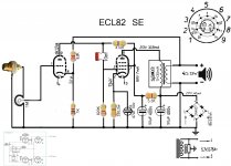
Elevated heaters are done! Everything seems fine. It was in fact very straight-forward, I should have studied valve wizard link more carefully. Now the volume pots seem a bit 'too strong', will tweak it and update schematic...
this is close to your amp also has the same 820 ohm resistor like yours
Flea Power Vacuum Tube Amplifier - Tiny 3 Watt SE Amp
Flea Power Vacuum Tube Amplifier - Tiny 3 Watt SE Amp
That amp looks very much alike. I hope to increase my understanding by looking at the differences, for example:
I wonder, why there is 220uf cap and 560R on cathode while on this one it is only 50uf and 330R?
I would also like to double power caps but don't know what resistors to use.
Any idea?

I wonder, why there is 220uf cap and 560R on cathode while on this one it is only 50uf and 330R?
I would also like to double power caps but don't know what resistors to use.
Any idea?
The resistors aren’t needed. Class A amplifiers doesn't require as much capacitance as class B amps. I would only add the first capacitor on the left side of your schematic.The cathode cap you can calculate it’s probably big enough. Getting to Know the Bypass Capacitor, January 1962 Popular Electronics - RF Cafe
- Status
- Not open for further replies.
- Home
- Amplifiers
- Tubes / Valves
- Yet another ECL82 se