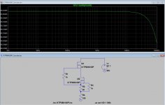
Designing an HV shunt regulator need a good CCS, surprisingly cascode DN2540 do not give very good results, googling I found an excellent reference (as ever)
CCS: not everything that glitters is gold (Part I) | Bartola Valves
Taking Ale's approach, with the same mathematical models I found the same as him (Duh), anyway I took the idea, thanks Ale!


The expression (Also robbed from Ale)
100*(1 - V(Out))/V(Out)
Came from a resistor divider and a little of algebra.
As I need a 100mA CCS, mathematical models from Supertex does not help, so looking for another solution, I found


Voltage source results from [300V (input) - 250V (output)]
I tried other models for the MOSFET and the results worsen a little, but not that much.
If I missed something, I will thank for some critics. 🙂
CCS: not everything that glitters is gold (Part I) | Bartola Valves
Taking Ale's approach, with the same mathematical models I found the same as him (Duh), anyway I took the idea, thanks Ale!
The expression (Also robbed from Ale)
100*(1 - V(Out))/V(Out)
Came from a resistor divider and a little of algebra.
As I need a 100mA CCS, mathematical models from Supertex does not help, so looking for another solution, I found
Voltage source results from [300V (input) - 250V (output)]
I tried other models for the MOSFET and the results worsen a little, but not that much.
If I missed something, I will thank for some critics. 🙂
Why not just use Walt Jung's circuit with Bias Multiplier as Ale suggests?
Also.. I wonder if a "gyrator" will give better results?
Also.. I wonder if a "gyrator" will give better results?
Last edited:
Why not just use Walt Jung's circuit with Bias Multiplier as Ale suggests?
Hi, thanks for your input.
With Walt Jung's circuit with Bias Multiplier is pretty much the same


Also.. I wonder if a "gyrator" will give better results?
From Walt Jung interview
That's why I need a CSS with very high resistance.As far as I know, a gyrator is a kind of SS inductance, really do not know if it will work as a high resistance CCS.In audioXpress, November and December 2009, Didden interviewed Malcom Hawksford on various audio topics. Within part one, Hawksford made a valuable point related to power supplies, which is that a shunt-type regulator localizes audio dynamic currents. Going further on this theme, in contrast, a series-type regulator returns dynamic audio currents all the way back to the raw DC supply! The latter type uses a long-series loop, as opposed to the short loop of a shunt. For audio, there are some profound implications to these differences.
Now, we all know that all series circuits (by their nature) carry the same
current at all points along the loop, both in the hot and ground legs. So, with a series regulator, the output signal current from an op-amp or other singleended active stage—it doesn’t matter whether it is tube, transistor, or whatever—will flow back through the regulator, and the raw-supply rectifiers. Or, if there is no regulator used, the audio currents still flow back through the raw supply.
Last edited:
I simulated the gyrator and it did not perform better.
It appears to me that what we are trying to achieve is rejection of signal riding on B+. This will mostly be line frequencyX2 + harmonics from PS.
Harmonics fall off rapidly so they don't need as much attenuation at higher frequency than the fundamental and early harmonics.
How much rejection is "good enough"? 90dB?
Shunt Regulator
Here is the idea

Searching for mathematical model issues, clearly MOSFET models are not very optimistic for this application, Gary Pimm claims 20Gohm at 100Hz with the IRF820


Performance with the IRF830 model is far worse.
So, what makes the OP-Amp controlled CCS behaves so good? 😕
As far as I know the model for NE5534 is quite accurate.
Here is the idea
Searching for mathematical model issues, clearly MOSFET models are not very optimistic for this application, Gary Pimm claims 20Gohm at 100Hz with the IRF820
Performance with the IRF830 model is far worse.
So, what makes the OP-Amp controlled CCS behaves so good? 😕
As far as I know the model for NE5534 is quite accurate.
Hi, thanks for your input.
This is my guess also.
For a shunt regulator intended for a stage with only 6dB PSRR (or less...), the bigger, the better, I would be very happy with more than 100dB.
I simulated the gyrator and it did not perform better.
This is my guess also.
It appears to me that what we are trying to achieve is rejection of signal riding on B+. This will mostly be line frequencyX2 + harmonics from PS.
Harmonics fall off rapidly so they don't need as much attenuation at higher frequency than the fundamental and early harmonics.
How much rejection is "good enough"? 90dB?
For a shunt regulator intended for a stage with only 6dB PSRR (or less...), the bigger, the better, I would be very happy with more than 100dB.
Hi Poplin
I am trying to reproduce this now.. in LTSpice with DN2540 as well as with IXTP08N100P (of which I have a very few).
This might sound a very trivial question, but what plot settings are you using? I Keep getting dB vs. Frequency.. Feeling a bit sheepish right now..
I am trying to reproduce this now.. in LTSpice with DN2540 as well as with IXTP08N100P (of which I have a very few).
This might sound a very trivial question, but what plot settings are you using? I Keep getting dB vs. Frequency.. Feeling a bit sheepish right now..
Attachments

move your mouse over the left scale and right click it. You will have options for Linear, Log, and Decade. Select linear.
Hi Poplin
I am trying to reproduce this now.. in LTSpice with DN2540 as well as with IXTP08N100P (of which I have a very few).
This might sound a very trivial question, but what plot settings are you using? I Keep getting dB vs. Frequency.. Feeling a bit sheepish right now..
Hi Soulmerchant
I think you plotted
100*(1-V(n001))/V(n006)
Instead of
100*(1-V(n006))/V(n006)
It comes from a voltage divider

From Ohm's law
U = I (R1+R2)
Rearranging
R1 = R2 (1-Un) / Un
With cascode DN2540, your plot gives about -390dB, after right click on the left scale and selecting linear, it gives 0.0mohm.
Yes, I realized all this in the last post... also the linear scale. Anyway look above. kind of sad when you consider the price of those parts, but maybe its an easier solution?
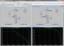
Ok, part of my error was the mistake in my expression. Here is IXTP08N100P cascaded again...
How do you like this plot? Too bad they are so darned expensive....
You think a lot faster than me!
I have problems with Internet today, but this is not an alibi. 😛😀
Yes, I think that DN2540 are better.BTW make right click on the left side of the scale in your plot, and then select linear, results are in Ohms.
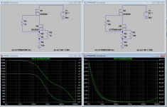
ugh.. forget my last post.. I am still tinkering with it to get the load right for the IXTP device. I wanted to just use it as the bottom device, but the results are now not making sense. Maybe I need to re-check my model.
anyway here is what I get.
anyway here is what I get.
Attachments
Last edited:
Yes, clearly DN2540 is a better device, you work at about 38mA, I must reach 100mA, so far the complex version IRF830 OP-AMP controlled is my only chance.
The thing is that I do not know why! 😛😀
Big problem is that I have only and old scope and two multimeters, LTSpice is my silver bullet.
The thing is that I do not know why! 😛😀
Big problem is that I have only and old scope and two multimeters, LTSpice is my silver bullet.
Last edited:
Ok, for fewer than 35mA's the IXTP08N100P device is looking very good though. I see your need is different though.
IXTP01N100D might be very interesting for your application. Just need to get together a spice model for it...
IXTP01N100D might be very interesting for your application. Just need to get together a spice model for it...


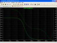
Mystery Solved (Almost)
Mathematical model used in post#1
Another one with some capacitance added to fit better with datasheet
***** NE5534 Source: Texas Instruments
* C2 added to simulate uncompensated frequency response (Uwe Beis)
With the "corrected" model, results are worse
Mathematical model used in post#1
Code:
* NE5534 OPERATIONAL AMPLIFIER "MACROMODEL" SUBCIRCUIT
* CREATED USING PARTS RELEASE 4.01 ON 04/10/89 AT 12:41
* (REV N/A)      SUPPLY VOLTAGE: +/-15V
* CONNECTIONS:   NON-INVERTING INPUT
*                | INVERTING INPUT
*                | | POSITIVE POWER SUPPLY
*                | | | NEGATIVE POWER SUPPLY
*                | | | | OUTPUT
*                | | | | |
*                | | | | |
.SUBCKT NE5534   1 2 3 4 5
*
  C1   11 12 7.703E-12
  DC    5 53 DX
  DE   54  5 DX
  DLP  90 91 DX
  DLN  92 90 DX
  DP    4  3 DX
  EGND 99  0 POLY(2) (3,0) (4,0) 0 .5 .5
  FB    7 99 POLY(5) VB VC VE VLP VLN 0 2.893E6 -3E6 3E6 3E6 -3E6
  GA    6  0 11 12 1.382E-3
  GCM   0  6 10 99 13.82E-9
  IEE  10  4 DC 133.0E-6
  HLIM 90  0 VLIM 1K
  Q1   11  2 13 QX
  Q2   12  1 14 QX
  R2    6  9 100.0E3
  RC1   3 11 723.3
  RC2   3 12 723.3
  RE1  13 10 329
  RE2  14 10 329
  REE  10 99 1.504E6
  RO1   8  5 50
  RO2   7 99 25
  RP    3  4 7.757E3
  VB    9  0 DC 0
  VC    3 53 DC 2.700
  VE   54  4 DC 2.700
  VLIM  7  8 DC 0
  VLP  91  0 DC 38
  VLN   0 92 DC 38
.MODEL DX D(IS=800.0E-18)
.MODEL QX NPN(IS=800.0E-18 BF=132)
.ENDS NE5534***** NE5534 Source: Texas Instruments
* C2 added to simulate uncompensated frequency response (Uwe Beis)
Code:
* NE5534 OPERATIONAL AMPLIFIER "MACROMODEL" SUBCIRCUIT
* CREATED USING PARTS RELEASE 4.01 ON 04/10/89 AT 12:41
* (REV N/A)      SUPPLY VOLTAGE: +/-15V
* CONNECTIONS:   NON-INVERTING INPUT
*                | INVERTING INPUT
*                | | POSITIVE POWER SUPPLY
*                | | | NEGATIVE POWER SUPPLY
*                | | | | OUTPUT
*                | | | | |
*                | | | | |
.SUBCKT NE5534   1 2 3 4 5
*
  C1   11 12 7.703E-12
  C2    6  7 3.500E-12
  DC    5 53 DX
  DE   54  5 DX
  DLP  90 91 DX
  DLN  92 90 DX
  DP    4  3 DX
  EGND 99  0 POLY(2) (3,0) (4,0) 0 .5 .5
  FB    7 99 POLY(5) VB VC VE VLP VLN 0 2.893E6 -3E6 3E6 3E6 -3E6
  GA    6  0 11 12 1.382E-3
  GCM   0  6 10 99 13.82E-9
  IEE  10  4 DC 133.0E-6
  HLIM 90  0 VLIM 1K
  Q1   11  2 13 QX
  Q2   12  1 14 QX
  R2    6  9 100.0E3
  RC1   3 11 723.3
  RC2   3 12 723.3
  RE1  13 10 329
  RE2  14 10 329
  REE  10 99 1.504E6
  RO1   8  5 50
  RO2   7 99 25
  RP    3  4 7.757E3
  VB    9  0 DC 0
  VC    3 53 DC 2.700
  VE   54  4 DC 2.700
  VLIM  7  8 DC 0
  VLP  91  0 DC 38
  VLN   0 92 DC 38
.MODEL DX D(IS=800.0E-18)
.MODEL QX NPN(IS=800.0E-18 BF=132)
.ENDSAttachments
- Status
- Not open for further replies.
- Home
- Amplifiers
- Tubes / Valves
- Yet another CCS