I am putting together my smaller components into the chassis for an amplifier, but I need to know where all of those pesky grounds go! I know this has been discussed before, but I seem to have an extra "odd ball" component with the input board.
I have included a picture showing what connections I have made so far (not much), and what connections I have not yet made. Could y'all help me with these questions?:
I am uncertain where to connect the shield on the wire from the input board to the main amplifier board
I have not shown the output - ("output minus") terminal (it is also a ground). Where does this connection go?
Do I make my star point ground at the chassis/system ground, or at the power supply ground (where the center tap of the transformer meets the common terminals of the electrolytic filter caps)?
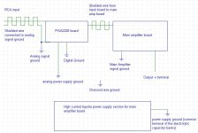
Attachments
Grounding
I do not have all the technical knowledge to give a well founded answer. However I can comment from my own experience.
First of all you should look at the currents which will flow trough the various grounds. High current flows should be kept as short as practical.
After that I hook all my grounds except ground from signal In to that point.
Signal In ground I located near to signal in the pcb to keep maximum shielding.
In my projects I did separate Earth ground from any signal ground.
The casing was grounded to Earth via the IEC connector.
Good luck
Jos
- Status
- Not open for further replies.