
"What do you think about this circuit: "
I think I would like to see the whole schematic.
Your post shows only a portion of the schematic.
Aud_Mot
I think I would like to see the whole schematic.
Your post shows only a portion of the schematic.
Aud_Mot
Amp
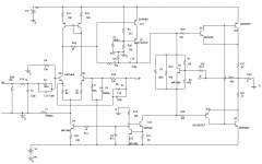
There is an inherent DC inbalance in the input differetial pair due to the DC feedback loop being down a diode drop on one side. Current feedback toplogies don't like a compensation cap across the feedback resistor. Kind of strange high frequency compemsation around cascode voltage gain stage. You would be better off with voltage feedback.
H.H.
Aud_Mot : I'm really sorry. I will fix this.
HarryHaller:
1) Q8 works to correct the ambalance. The base of this transistor is connected to de DC sample of the output(the signal is filtered with the RC circuit). I mean, for the DC, the imput circuit work like a diferential one. For the signal, like a current feedback imput circuit.
2) The compensation is the pole/zero strategy. The zero is for cansel the dominant pole, and the second pole (in a higer frecuency) make the amp stable.
3) Interesting: why don't like caps to the current feedback ???
Regards.
Attachments
I have mentioned this previously, but put a resistor in
series with the base of Q13 so that it doesn't drag down
your reference when you saturate on a negative clip.
series with the base of Q13 so that it doesn't drag down
your reference when you saturate on a negative clip.
Edgardo Cavalli said:Aud_Mot : I'm really sorry. I will fix this.
HarryHaller:
1) Q8 works to correct the ambalance. The base of this transistor is connected to de DC sample of the output(the signal is filtered with the RC circuit). I mean, for the DC, the imput circuit work like a diferential one. For the signal, like a current feedback imput circuit.
2) The compensation is the pole/zero strategy. The zero is for cansel the dominant pole, and the second pole (in a higer frecuency) make the amp stable.
3) Interesting: why don't like caps to the current feedback ???
Regards.
In CFB amp a cap across the feedback resistor will make the amp have "infinite" gain at high frequencies. So at the point where you wan't less than 1 times gain through the amp (at 180 degrees phaseshift) to prevent oscillation you will have a gain higher than one. You amp will become unstable.. some times it oscillates other times not (Wave you hand magic!)
Sonny
Amp design
You have Q9 and Q8 biased at about 1.5 mA each by the current source. You are injecting -.65 volts /1000 ohms or about 0.65 mA into the emmiter of Q9 when the output of the amp is at 0 volts. Is this going to work for low DC offset? C4 is coupling power supply noise into your feeback node. I have not figured out why C1 and R19 are in the circuit. Say..... you weren't going to hook this up to expensive speakers were you? I never got invited to design reviews at work very often which is sad because I enjoy them so much....
You have Q9 and Q8 biased at about 1.5 mA each by the current source. You are injecting -.65 volts /1000 ohms or about 0.65 mA into the emmiter of Q9 when the output of the amp is at 0 volts. Is this going to work for low DC offset? C4 is coupling power supply noise into your feeback node. I have not figured out why C1 and R19 are in the circuit. Say..... you weren't going to hook this up to expensive speakers were you? I never got invited to design reviews at work very often which is sad because I enjoy them so much....
Mr Pass: thanks, i'll fix that.
HH:
C1 is there to give a gound reference to the feedback network.
R19 provide some variation to the polarization voltage for the output stage.
I see some circuits from Mr Pass (US Patent Nr 3,995,228) and try the circuit (in a variation) in the PSpice. The THD was lower, so i let the resistor.(not so cientific, but....)
You right with C4 and C11. May be better if they are connected to ground insted of -VCC.
Unbalance: The realimentation make colector current of Q9 and Q8 tends to be equal, so the unbalance is produced in the emmiter resistors. The PSpice give an output DC voltage of 42mv.
Anyway, before i connect the speakers, i will use the voltmeter (just in case!).
Sonnya:
With respect to C12, according with my knowledge (no to much), the gain in this circuit is (R5//Z(C12))/R6 +1. So when f-> infinity, the gain -> to 1 (is that right???)
C4 & C11....
Gnd, -Vcc. What difference will it make.
C1 is a ground reference? AC ground and ramp generator, more like.
What is R10 doing across the bias spreader?
The schematic is still wrong. And everyone wonders why I hate Spice.
Jocko
Gnd, -Vcc. What difference will it make.
C1 is a ground reference? AC ground and ramp generator, more like.
What is R10 doing across the bias spreader?
The schematic is still wrong. And everyone wonders why I hate Spice.
Jocko
Amp design
You need to learn to swim before you jump head first into the deep end of the pool. Here are some sources for amp design theory. Build something that is a proven design. Current feedback amps not the place to start for beginers.
http://www.engin.umich.edu/group/ctm/freq/freq.html
http://www.dself.demon.co.uk/ampins.htm
http://sound.westhost.com/index.html
Good Luck.
H.H.
Actually, I think there is some merit to current feedback
in the hands of beginners. The impedance of the feedback
loop is high enough to limit the open loop gain of the
circuit, and all other things being equal, will probably
be a more stable amplifier.
in the hands of beginners. The impedance of the feedback
loop is high enough to limit the open loop gain of the
circuit, and all other things being equal, will probably
be a more stable amplifier.
Re: Amp design
Boy Harry, that first link sure brought back some memories!
Mathlab didn't mean anything like that when I was there years ago. 🙂
Obligatory picture:
mlloyd1
Boy Harry, that first link sure brought back some memories!
Mathlab didn't mean anything like that when I was there years ago. 🙂
HarryHaller said:.... Here are some sources for amp design theory....
Obligatory picture:
mlloyd1
Attachments


Nelson Pass said:Actually, I think there is some merit to current feedback
in the hands of beginners. The impedance of the feedback
loop is high enough to limit the open loop gain of the
circuit, and all other things being equal, will probably
be a more stable amplifier.
Yes if you do not add caps to the feedback loop the i will agree with you. It is easy to control the phase margin by changing the size of Rf.
Sonny
CFB amps & beginners
Yes, Sonny, but what about in non-inverting mode, hmmmmm?
"I outrank you!"
Jocko
Yes, Sonny, but what about in non-inverting mode, hmmmmm?
"I outrank you!"
Jocko
CF revisted
http://www.diyaudio.com/forums/showthread.php?threadid=1929&highlight=currentfeedback
Is this is the same Sonny that said the following about C.F.?
"There is something to chance ... It is not DIY friendly!!!!"
Everybody raise thier hands who know what an adequate phase margin is.
You know your movies Nelson, but I can stump you another time.
Harry you forgot : "It can be made a lot simpler. And i did have problems with the inputbuffer ... It worked like a "mixer" you know the ones they user in FM receivers!!!! I have made lowpass filter in the input to get loose of the problem."
😉
That was what i did have in mind with the words : "There is something to chance ... It is not DIY friendly!!!"
What about 60 - 70 degress of phase margin into 8R||1uF ?? This should give you a nice stable amplifier with most loads.
For Jocko .. I think it is still Rf who controls the Bandwidth/phasemargin of the amp when runing in noninverting mode ?
Taken from ti slod006a applicationnote page 8.6 : "CFA inverting and noniverting has identical stability equations"
That's not my words!
hehehehe .........
- Status
- Not open for further replies.
- Home
- Amplifiers
- Solid State
- Yes!, another amp