Hi all...
Just had to say somthing about this since im sooo supprised that it worked out first time.
Ive managed to add 3 SPDIF optical outputs to my Revo7.1 card by tapping the AKM4355 I2S lines (the AKM4355 had to be removed though).
I could have added 4 SPDIF outs, but i wanted to keep the original front outs for headphone/misc use.
This will be used for the brutefir active xover + room-eq stuff in my linux box.
Next ill be building a new 6 channel DAC with rectified bridged gainclone amp outputs.
Ive taken some photos of the card:
http://www.overclockers.com.au/~mwp/gallery/thumbs.php?sub=My DIY/MAudio Revo SPDIF Mods
If anyone wants to do somthing similar, let me know and ill put the schematics/pcb diagrams up.
I'd love to get some more over this...
I have an audiophile 2496 and need one more spdif out(coax) for a separate stereo DAC.
BWT, that's really cool what you did over there
I have an audiophile 2496 and need one more spdif out(coax) for a separate stereo DAC.
BWT, that's really cool what you did over there

And people call me crazy for changing a couple of OP-amps on my Revo... 😱
This is really cool. I might be interested in doing something similar on my Revo in the future. But I would probably try to use balanced twisted pair as outputs which connects to some DIY DAC:s close to the rest of of my stereo.
It seems from your pictures that the original DAC is fed with data from three separate wires, one for each stereo pair. Is this correct?
This together with the thread 'PC-music player' really opens up for interesting uses of the PC. Thanks for sharing this.
--- Mikael R
PS. Off topic but like to mention http://www.musicpd.org/ and http://www.netjuke.org/
Some good program for a music playing linux box. .DS
Blue_Max said:How to add more Coaxial S/PDIF electrical digital inputs?
Cant.
Originally posted by Blue_Max
How to add more Coaxial S/PDIF electrical digital inputs?
MWP said:Cant.

Hey that's really nice. I've been thinking along the same lines, but I don't know how to use ALSA to make sure that all the streams are synchronized. Do you have any code along these lines?
-jwb
-jwb
jwb said:Hey that's really nice. I've been thinking along the same lines, but I don't know how to use ALSA to make sure that all the streams are synchronized. Do you have any code along these lines?
I use JACK and havnt had any problems.
Although i cant really tell without a scope to test it with.
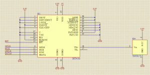
MWP said:Here is a screen cap of the schematic.
There are three of this exact circuit on the PCB with a few power smoothing caps.
Power (3.3V and 5V) is taken off the Revo.
Hi MWP,
sorry to bother again: could you please share schematic and PCB/gerbers files too?
Maybe they are to big to be uploaded here, I'll send you a PM with my e-mail address🙂
- Status
- Not open for further replies.
- Home
- Source & Line
- Digital Source
- Yay! MAudio Revo modded for 3 SPDIF outputs
