n_maher said:So I put in another fuse, disconnected the speakers and tried again....
Question: what should I be measuring for resistance across the outputs with no power applied? I'm getting essentially a short condition and that doesn't see quite right to me but it's the same for both transformers...
You don't want to run a tube amp with no load on the outputs. Keep a pair of junk speakers, or a cement resistor dummy load connected at all times.
A good output transformer should have a DC resistance of 50 to 500 ohms on the primary side. The secondary side will have a few tenths of a ohm DC resistance. If either side measures open circuit, that's bad. If there is no resistance (aka, short circuit) between primary and secondary, that's bad too.
They are indeed floating. I haven't tried to measure to see if the primary is shorted to the secondary but what I am saying is that when I measure the resistance across the binding posts from the positive to negative post I get .7ohm.w5jag said:I thought your OPT cases were floating above ground? If they are above ground, how can they pop your power supply unless the OPT primary is shorted to the secondary?
So I'm either measuring something wrong, have something hooked up incorrectly or the output trafos are toast. It seems unlikely that I have something incorrectly wired since the amp function just fine for two rounds of testing and then for around an hour last night before fizzing out. I based my output wiring on information that I received from the person that I bought the trafos from which I assumed to be correct. Unfortunately Electraprint does not publish schematics for the trafos that I have and their "standard" wiring scheme uses the same color for all sorts of different functions.
FWIW my output trafos have an Orange and Green wire exiting on one side, which I'm told is the 60ohm secondary and have a White, Blue and Red wire exiting the other side which should be the primary (blue and red) and the ultralinear tap (white). I have the UL tap disconnected for now and I reconfirmed that it isn't shorting against anything.
So my next question would be that since the trafos appear to be reading correctly should I step up to a slightly larger fuse and see what happens. I full disclosure, I'm unsure of whether or not the 2A fuses that I have are slo or fast blow types. I wish I had some other 2A's to try but the next level I have is 4A and again I don't know which type they are. 
(2A)(117V) = 234 watts, so 2A should be fine.
I use a 2A fast blow in my Simple SE and Tubelab SE. I want the fuse to blow fast if something is wrong.
How often do you read about people having shorted OPT's? I don't keep up with the hi-fi world much, but I don't recall ever hearing about that. Crummy sound maybe, but not catastrophic failures.
I look to parts that are known to fail frequently - new manufacture rectifiers (aka junk), caps, things like that, and exhaust those possibilities before I go on to less common failure parts.
Hopefully, someone with more knowledge about hi fi amps will have a more specific suggestion for you.
Win W5JAG
I wouldn't use a 4 amp fuse. Even a fast blow 2 amp should be fine. Your rectifier tube is a 5AR4/GZ34, correct?
If there are only five wires on the output transformer, it should be easy to determine what is what. The two with <1 ohm between them is the secondary. That side goes to the speakers, of course.
The two of the other three wires will have somewhere around 50 to 500 ohms between them. Find the pair (of the three) that has the largest DC resistance. Those are the "ends" of the primary winding. The one that is left over is the center (ultralinear) tap.
DC resistance measurements ought to be similar between the two transformers.
Do you happen to have another 5AR4 to try?
It happened to me twice that the 5AR4's were tested good but blew the fuse upon start up.
It happened to me twice that the 5AR4's were tested good but blew the fuse upon start up.
Ok, all appears to be well with the amp, at least in a brief 15 minute test. I'm going to try a good long stress test tonight while I work on other projects so I can be close by if something goes wrong again.
I did replace the 5AR4 that I had been using, my suspicion is that there was an issue caused by the SS rectifiers that may have damaged the previous 5AR4. This may have also been partly a result of the marginal EL34s. I still can't explain why the caps are measuring the way that they do in circuit and wish that I could. Basically if I measure C2 it measures ~250uF and C1 doesn't like to measured at all. If anyone has any bright ideas I'm all ears. I'm not 100% sure that I measured them in circuit before the first time I tested the amp, I'm only sure that I measured them before attaching them to the circuit board.
I did replace the 5AR4 that I had been using, my suspicion is that there was an issue caused by the SS rectifiers that may have damaged the previous 5AR4. This may have also been partly a result of the marginal EL34s. I still can't explain why the caps are measuring the way that they do in circuit and wish that I could. Basically if I measure C2 it measures ~250uF and C1 doesn't like to measured at all. If anyone has any bright ideas I'm all ears. I'm not 100% sure that I measured them in circuit before the first time I tested the amp, I'm only sure that I measured them before attaching them to the circuit board.
0.7 ohm is normal for a resistance reading across the speaker terminals. This reading varies from 0.3 to 1.5 ohms depending on the wire size used in the transformers. A lower reading means a heavier wire is used in the transformer secondary, which is usually a good thing.
From my experience you probably have a toasted 5AR4. The startup conditions are hard on the rectifier tube, and some current production tubes aren't the highest of quality. Several people have had problems with JJ or Sovtek, while other users report great results. I bought 6 Sovtek 5AR4's a few years ago and all are still going strong. One used had 2 fail instantly yet the third has lasted nearly a year.
It is also possible that one of the FRED's have failed. Try removing them if you haven't already. A bad FRED will usually blacken the fuse instantly on power up though.
The fuse in the Simple SE should be 2 amp for 120 volt countries, and 1 amp for 240 volts. 4 amps is a risk for frying the power transformer if there is an excessive current situation.
An "inrush current limiter" like the CL-70 can be added in series with the transformer primary to reduce the turn on surge. I plan to add this to the assembly manual if I am ever home long enough to update it. For more info see this thread:
http://www.diyaudio.com/forums/showthread.php?s=&threadid=74377&highlight=
In circuit capacitance readings can be confused by the inductance of the choke. Remove all tubes, disconnect one wire of the choke and you should get better readings. Or since you got it working while I was typing my last response, just listen to it and forget about capacitance readings.
tubelab.com said:In circuit capacitance readings can be confused by the inductance of the choke. Remove all tubes, disconnect one wire of the choke and you should get better readings. Or since you got it working while I was typing my last response, just listen to it and forget about capacitance readings.
Thanks! I must admit that it was reading replies like the one above that got me really psyched about working on this project, I love the no BS approach. 😀
Ok, we're 1.5+ hrs into tonight's stress test and so far so great. Time to figure out how to fabricate some feet for this chassis and then I think I can leave well enough alone for a while. At least until I get tempted by ultralinear and feedback options. 😎
Nothing new to report here, other than the amp passed another successful stress test last night and performed flawlessly for multiple hours. I'm quite impressed with the sound using the Gold Lion reissue KT88s.
For tubelab.com - the part number for the vibration isolation grommets is 9311K139 from McMaster Carr. And feel free to use the pictures any way you'd like. I tried to email you links to higher-res versions but can't, if you'd like them just shoot me a message.
For tubelab.com - the part number for the vibration isolation grommets is 9311K139 from McMaster Carr. And feel free to use the pictures any way you'd like. I tried to email you links to higher-res versions but can't, if you'd like them just shoot me a message.
feel free to use the pictures any way you'd like.
Thanks, it looks like the pictures posted here are about the same size that I usually post on my web site. There are users out there that are on dial - up, even with the resolution that I use, some people report 5 minute page loads on some of the assembly manual pages. I will email you when I get back home (next year) if I need better ones.
George, If you want to use my pictures, you just have to go at this adress
http://picasaweb.google.ca/TigrineAudio/SimpleSe#
http://picasaweb.google.ca/TigrineAudio/SimpleSe#
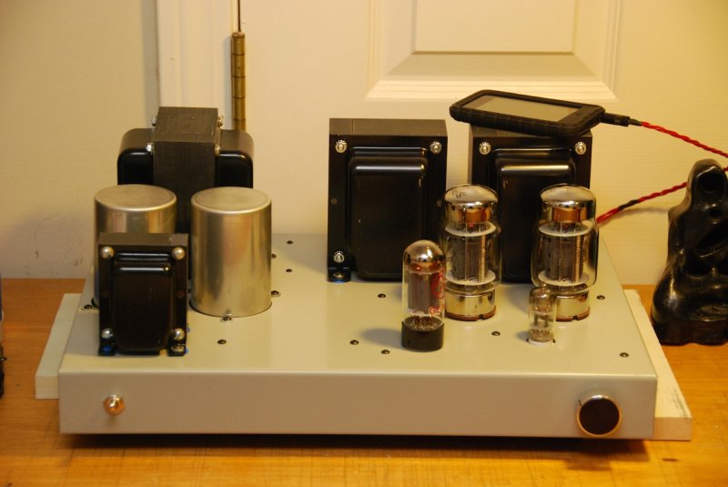
Here's the amp installed in my soldering rig, fed for now by my Ipod Touch (soon to be replaced with an Apogee Duet) and driving my Ascend Acoustics CBM-170s (soon to be replaced with DIY single driver bookshelfs).
overall

closeup
glowing

overall
closeup
glowing
... and another!
Built my Simple SE over the last week - chose this thread to post but there are others around!
Briefly used:
Hammond 374BX Power Transformer
Transcondar 5k OPTs
Changed the PS to be CLCRC 22uf, 4H choke, 165Uf, 65ohm resistor, 330uf. Using PSUD this has much better ripple reduction than a costly large choke in a CLC filter. Caps are all 2@350v caps in series with balancing resistors (which also act as bleeder resistors) to get 700v rating, easier to get and cheaper than large 500+v caps.
Otherwise built as per circuit diag. No Utralinear, not using cathode feedback so far.
Tubes are Groove Tube EL34M, Philips JAN 12at7, Sovtek 5AR4. Impressed by the slow ramp up of the 5AR4, I had gone for the higher voltage caps partly 'co of the higher voltage you get as PS ramps up fater with no load (other tube rectifiers or SS).
Sounding very clean, very strong bass. I have recently built both Aleph Mini and an RH84 - I would say this is closer to the Aleph from initial listening impressions.
Had an interesting problem when first tested with 20v on the grid (and 50v on the cathode) of one channel. After much angst I found one of the Russian PIO interstage caps was "leaking" 20v. Replaced it and both cathodes reading 32v (B+ 445v as predicted by PSUD). Never experienced this one before!!
OK, couple of pics. BTW layout largely based on Ty Bowers build (thanks Ty), I much prefer the smaller width approach.
Attachments


ChrisMmm said:...and
Also, I am thinking of getting some Genalex Gold Lion KT88 tubes Valves, they are getting some good comments around the place but are a bit pricey. Any experience with these or any other suggestions??
Cheers
I am breaking a set in on my SimpleSE right now that I got for Xmas. They replaced a set of cheap Chinese 6L6GC's. There seems to be much better bass so far. Both tubes really sound great though.
cjkpkg said:
I am breaking a set in on my SimpleSE right now that I got for Xmas. They replaced a set of cheap Chinese 6L6GC's. There seems to be much better bass so far. Both tubes really sound great though.
Thanks, they are quite big $s so wanted to be sure.
BTW, I just realised my pics had the EI EL34s I used initially. Just did some listening at fairly loud levels with the GT tubes and I think the bass with them is cleaner and punchier than the EI. The GTs are replicas of the Mullard XF2 twin getter tubes in the same way as the Gold Lion are replicas of the Genalex KT88.
Question about tube dissipation
I have some questions around output tube dissipation, cathode voltage and current.
From George's website it would appear the target dissipation is around 27watts, varies a little with tube type. The 27watts is derived from plate voltage and current, current in turn can be derived by dividing cathode voltage by cathode resistor (am I correct so far?). So you can achieve the target dissipation by adjusting the cathode resistor to gain the appropriate current draw for the plate voltage.
I am using EL34s and in my case I have a B+ of 445v, given OPT primary of 5k I would have about 430v on the plate (this in turn being dependant on current draw so maybe up to 433V, I forgot to measure it!). I measure 32v across the cathode resistor which is 560ohm. This current draw is 57ma multiplied by plate voltage gives me around 24.6watt dissipation. This is a bit below the 27watt target. Should I lower the cathode resistor? I have a 510ohm pair which should give me another watt or so dissipation.
Looking at George's power output simulations the EL34 show the combination of 450v B+ and 560ohm resistor should give 28watt dissipation. Is this the appropriate target for that tube? How important is this for optimal performance?
Cheers
- Status
- Not open for further replies.
- Home
- More Vendors...
- Tubelab
- YASSE - Yet Another Simple SE Build