Hi all MC-10L owners, have you suffered an EL34 burn out and it happened to be the left channel? More interestingly - was it V3?
I have a theory which I hope to investigate over the weekend.
You see, I was reviewing my Yaqin MC-10L Guide and wondered if I could do a component ident chart for the newer Mark 2 and 3 circuit boards. However, try as hard as I might, I could not see the location of R6 on the left hand output board. My guide shows it hidden under wiring on the early models but I am having doubts about this. All of the photos I have of my early amp, and photos given to me by owners of newer models, just did not clearly show R6.
I did a count - yes 6 small resistors on the right hand side but only 5 on the left hand side. I am going to have to take my amp apart to solve this mystery but my suspicions are that R6 is hidden underneath the chassis supporting the mains transformer. Worse than this is fear that this resistor may be placed too close to the metal work. What if it shorted to chassis?
Well it would lower the bias on V3 which would start to draw excess current to the point of failure. I may just be talking nonsense until I visibly check R6 out, but there just has to be a reason why Left Hand channels fail so often so I am wondering if this could be a possible reason for it.
If anyone has their amps top cover removed and can check the positioning of R6 I would be grateful. There is the possibility that the Mk 2 and 3's are different to the Mk.1 in layout but I sure still find R6 hiding on all photos.
Regards
Les
Attachments
Last edited:
I believe it is the fitting of a push button switch and change of front panel from dark plastic to aluminium but there may be other changes internally. The Mk.1 had to be dismantled to check bias, the Mk.2 provided external test points and access to bias controls yet retained the supply toggle switch, dark panel and the high voltage capacitors were hidden away.
Hi-Q,
Thank you. I have two MC10-L's. Great amps for the money. Both have the push-button power switch so it would seem that they are Mk III's.
Thank you. I have two MC10-L's. Great amps for the money. Both have the push-button power switch so it would seem that they are Mk III's.
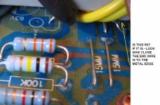
I have at long last dismantled my MC-10L and can confirm that R6 does indeed live under the power transformer in the position shown in the photo. You can see how R6 is leaned over to help it clear the metal work. I may have done this the day I first inspected the amplifier, a long time ago and long enough for my ageing grey matter to forget! So don't rely on this being done at the factory!
This item must come high on the list of possible reasons for left channel burn out!
This item must come high on the list of possible reasons for left channel burn out!
- Status
- Not open for further replies.