Hi Patrick Bateman,
I think I failed to effectively communicate my query.
I was able to determine Yamaha's design had some probability of being a high-Q resonator, based on the estimated dimensions and placement. Yamaha's specific resonator appears bereft of any visible labyrinth or plurality of structure.
See, this is where they lose me:
If the two devices' resonance correspond to one or two frequencies, who's effectiveness rapidly diminishes when moving upwards or downwards away from the tuning frequency due to a high-Q factor, how is the acoustic absorber capable of removing all frequencies that are immediately reflected back to the driver, beginning below 100Hz to twice the 750Hz lowpass frequency?
I may be viewing this in the wrong light, but I think it would require a myriad of acoustic paths with overlapping bandwidths, and these absorbers only appear to have a single path. Is it possible there is a more complex structure not revealed in their images?
Last edited:
Hi, yeah, at least to an extent. If depth of the box is great, then that would be the most problematic one. You can play with this stuff in hornresp.tmuikku,
So if the woofer is mounted in center of baffle (mid way top to bottom) then this is not an issue that needs to be resolved?
100Hz is 3.4m long, quarter is 85cm, pressure on a small box would be uniform, no standing wave, no problem.... beginning below 100Hz to twice the 750Hz lowpass frequency..
This was an arbitrarily chosen frequency for the sake of quick posting (it was late), but the focus is not only on lower frequencies.100Hz is 3.4m long, quarter is 85cm, pressure on a small box would be uniform, no standing wave, no problem.
My concern is the box acting like an echo or reverb chamber which reflects the sound of reproduced frequencies back on the woofer with delay, and the only things that are pictured to absorb the first and subsequent reflections are two tubes on the side walls, which do not appear to contain any plurality or other absorption technology. Virtually, the entire inside of the cabinet is shown as empty, save for a piece is thin foam on the underside of a brace.
If the woofer is reproducing a wide spectra of frequencies, what is stopping the back wall and other hard surfaces from immediately reflecting this delayed energy back towards the woofer cone?
Last edited:
Hi,
I see, you probably refer to pics found online, where it looks like there is no filling inside the cabinet?
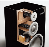
I haven't seen the speaker, let alone heard or seen the innards so hard to tell. Anyone have info if there is additional filling inside?
Either the tubes work really well or they have additional "normal" damping in there, despite there is none in the brochure cutout image. You could use both in your own speaker if you wish and find it improves performance.
If sound is great, then there is no problem. I had big bass boxes with ~200Hz xo and they definitely had noise/rumble, or mölinä in Finnish over the midrange, very audible. It was some combination of sound leaking through port, through cone, trough two screw holes that missed a bolt, panel resonances and so on. If sound is fine, you probably have no issues with these. You should be able to detect any mode that affects sound from impedance measurement or near field measurements and how they change if you add tube, "normal" damping or change position of the driver. Don't forget to caulck the box, use appropriate bracing, damping, consider port size and location inside and outside to reduce audibility of "noise" due to the construct. Make sure there is no obvious audible issues / problems and you should be good. If there is, add a magic bullet like tubes in yamaha ns500 to target some specific issue there is left.
Anyway, here is example with hornresp, which doesn't consider depth of the box, only length / width in this case.
Here is roughly similar sized box, driver in at the center and modes inside hornresp calculates. These are without any damping material added.
Lowest mode not visible, it cancels itself out.
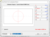
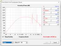
now everything the same lets move the driver to the end like with ns5000, now the lowest mode appears.
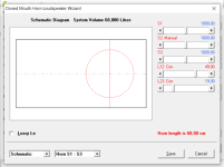
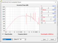
Here the same boxes with some arbitrary filling added to show how the resonances attenuate. If I saw a real measurement like this I'd now have a frequency to tune the additional narrow bandwidth damping tubes, the lowest mode. This would be roughly ~250Hz in case of driver at the end of baffle, or about ~500Hz if driver was on the middle.
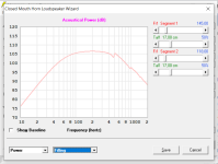
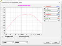
Depending on crossover frequency and steepness you might have nasty sound due to the modes inside as hornresp indicates. Positioning driver middle of the longest dimension would make lowest mode octave higher, perhaps making the sound fine, no need to address the 500Hz anomaly. Depending on other dimensions of the box this ought to work in reality as well, as long as depth is not too big.
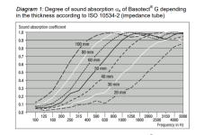
The driver would be at the end of "depth" dimension exciting those modes maximally. For this reason, it would make sense to reduce box depth until half wave resonance is at very high frequency, where damping material is effective to kill it. Damping materials I know of all have absorption coefficients so that they are low at low frequency and high at high frequency.
Hope it helps 🙂
I see, you probably refer to pics found online, where it looks like there is no filling inside the cabinet?

I haven't seen the speaker, let alone heard or seen the innards so hard to tell. Anyone have info if there is additional filling inside?
Either the tubes work really well or they have additional "normal" damping in there, despite there is none in the brochure cutout image. You could use both in your own speaker if you wish and find it improves performance.
If sound is great, then there is no problem. I had big bass boxes with ~200Hz xo and they definitely had noise/rumble, or mölinä in Finnish over the midrange, very audible. It was some combination of sound leaking through port, through cone, trough two screw holes that missed a bolt, panel resonances and so on. If sound is fine, you probably have no issues with these. You should be able to detect any mode that affects sound from impedance measurement or near field measurements and how they change if you add tube, "normal" damping or change position of the driver. Don't forget to caulck the box, use appropriate bracing, damping, consider port size and location inside and outside to reduce audibility of "noise" due to the construct. Make sure there is no obvious audible issues / problems and you should be good. If there is, add a magic bullet like tubes in yamaha ns500 to target some specific issue there is left.
Anyway, here is example with hornresp, which doesn't consider depth of the box, only length / width in this case.
Here is roughly similar sized box, driver in at the center and modes inside hornresp calculates. These are without any damping material added.
Lowest mode not visible, it cancels itself out.


now everything the same lets move the driver to the end like with ns5000, now the lowest mode appears.


Here the same boxes with some arbitrary filling added to show how the resonances attenuate. If I saw a real measurement like this I'd now have a frequency to tune the additional narrow bandwidth damping tubes, the lowest mode. This would be roughly ~250Hz in case of driver at the end of baffle, or about ~500Hz if driver was on the middle.


Depending on crossover frequency and steepness you might have nasty sound due to the modes inside as hornresp indicates. Positioning driver middle of the longest dimension would make lowest mode octave higher, perhaps making the sound fine, no need to address the 500Hz anomaly. Depending on other dimensions of the box this ought to work in reality as well, as long as depth is not too big.
The driver would be at the end of "depth" dimension exciting those modes maximally. For this reason, it would make sense to reduce box depth until half wave resonance is at very high frequency, where damping material is effective to kill it. Damping materials I know of all have absorption coefficients so that they are low at low frequency and high at high frequency.

Hope it helps 🙂
Last edited: