Hey, have Yamaha MX-600 stuck in protection mode. All outputs are out of circuit and still in protect mode.. What to check next or just rebuild protection circuit. Relay has been replaced and + and - voltages coming off of bridge to main caps..
Input greatly appreciated
Input greatly appreciated
Hi DWURM,
Welcome to the forum!
Please do not proceed with any of my suggestions unless you know how the test live circuitry safely. I don't want you to risk yourself or your equipment!
You mention having removed output devices. Would you be specific about which devices are removed, specifically output transistors versus drivers?
You've already confirmed supply rails to the amps? I wouldn't rebuild anything until your have measured the output voltages of both amps in front of the output relays. Most of the protection circuit monitors the DC outputs of the amps, so you should not expect the protection to clear unless amp offset voltages are behaving reasonably. Don't blindly change parts without having good evidence.
Would you advise the history of the amp? Recently failed or acquired in failed state, etc?
Please keep us posted. Good luck!

hey, thanks for reply... got amp in this condition, have pulled output transistors to check for shorts and vom shows all good, no shorts and no opens. the +60V rail is not getting through protection circuit... seems to be pointing to the zeners in protection... can't read the necessary voltages off of my schematic but here it is... +60 gets to relay but ends there..

Unless I've overlooked something, the relay blocks the speaker output in the event of a fault; the +/- 60V should be present at amp supply rails even when the amp is in protection state. If you're seeing 60V at a relay contact, that suggests that the amp output is stuck at the +60V supply rail and the protection circuit may be correctly preventing the faulty 60V from reaching the speaker terminals.
So, we need some voltage measurements with no load at the speaker terminals. Would you confirm +/-60VDC on the supply rails to both channels and would you report the output voltage for each channel, measured before the relay contacts? I'll follow up with more requests of measurements after this initial peek at the state of the amp.
Thanks.
As above, measure DC offset for each channel, between output emitter resistors, if in doubt measure at bias test points as per sm, ie, red probe on R87(either end) and black probe on chassis, expect less than 100mV. Repeat for right channel, ie R88 and GND.
good day, confirmed +64/-64 rails getting to collectors of output resistors checked voltage for, adjusted to 10mv per manual.. one channel was .09 and other .011vdc. pots allowed adjustment .010 for both channels 10mvdc. balls on.....
Are you saying the amp is now working? Or is it still stuck in protection? Output offsets looks very encouraging...
its still stuck in protection..... i've never dealt with a protection circuit.. seems can be triggered by numerous ways... just don't know where to look.. another observation is that am not getting the +64v off of the main board, down to power switch via a 4wire straight patch.. its not there so problem has to be on main board i would think... suggestions on where to measure or look are greatly appreciated. did close observations on all the components with bright light. no discoloration or traces of overheating anywhere... board looks clean..
Check/replace C44(220uf/6.3V) this appears to be for the power on mute timing with R123.
Q39 needs to be conducting, measure voltage at Q39base, expect about 0.6Vdc. Also diode test D31.
Also measure voltages at Q37b then at Q38b.
Q39 needs to be conducting, measure voltage at Q39base, expect about 0.6Vdc. Also diode test D31.
Also measure voltages at Q37b then at Q38b.
Maybe also check D32. If the 24 V Zener diode became a short, the supply voltage will be on both terminals of the relay coil.
I'm going to suggest you back up a bit. Do you still have the output transistors removed? With these out of the circuit, it appears the amplifier feedback is running open loop, and the output will be unpredictable. If you have confirmed the output transistors are good, put them back in.
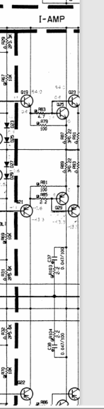
Now with the amplifier powered up, measure the voltage (to ground) at the junction of R117/R119 and the junction of R118/R120. Both points should be <100 mV. Now measure the voltage at the junction of R116/R131. This point should be between -40 and -45 volts. Finally. measure the voltage at the collector of Q31 (junction with R99) and Q32 (junction with R100). The readings here should be same as or just under the voltage on the +64 V rail.
Now with the amplifier powered up, measure the voltage (to ground) at the junction of R117/R119 and the junction of R118/R120. Both points should be <100 mV. Now measure the voltage at the junction of R116/R131. This point should be between -40 and -45 volts. Finally. measure the voltage at the collector of Q31 (junction with R99) and Q32 (junction with R100). The readings here should be same as or just under the voltage on the +64 V rail.
Just to confirm, both channels show only a few mV offset error at amp outputs and both amps show nominal bias currents adjusted via VR3 and VR4--- right? If so, good reason to believe amps are OK and problem is within protection circuit.
I'm not understanding what's being said here. There needs to be +64V present at the protection circuit, and -63V available to the MAIN(6) board. If you have trouble establishing that or if there's something about power switch, please clarify.
A few simple tests to localize the trouble spot within the protection section; please advise when behavior departs from what's projected, and we'll evolve test.
I assume the Protection LED is lit?
Make sure there are no speakers load or dummy loads connected.
Connect a jumper across Q40 collector to emitter. Relay RY1 should energize and the Protect LED should go dark. If this test is successful, remove Q40 jumper.
Short Q37 base to ground. After a few seconds, relay should energize and Protect LED should go dark. If this happens, the issue is likely associated with Q31 through Q36. To further localize, please measure voltages across R99 and R100. If more than a few mV are present, the problem is with the associated Q31 or Q32. Otherwise, with the other transistors and we'll troubleshoot further.
its still stuck in protection..... i've never dealt with a protection circuit.. seems can be triggered by numerous ways... just don't know where to look.. another observation is that am not getting the +64v off of the main board, down to power switch via a 4wire straight patch.. its not there so problem has to be on main board i would think... suggestions on where to measure or look are greatly appreciated. did close observations on all the components with bright light. no discoloration or traces of overheating anywhere... board looks clean..
I'm not understanding what's being said here. There needs to be +64V present at the protection circuit, and -63V available to the MAIN(6) board. If you have trouble establishing that or if there's something about power switch, please clarify.
A few simple tests to localize the trouble spot within the protection section; please advise when behavior departs from what's projected, and we'll evolve test.
I assume the Protection LED is lit?
Make sure there are no speakers load or dummy loads connected.
Connect a jumper across Q40 collector to emitter. Relay RY1 should energize and the Protect LED should go dark. If this test is successful, remove Q40 jumper.
Short Q37 base to ground. After a few seconds, relay should energize and Protect LED should go dark. If this happens, the issue is likely associated with Q31 through Q36. To further localize, please measure voltages across R99 and R100. If more than a few mV are present, the problem is with the associated Q31 or Q32. Otherwise, with the other transistors and we'll troubleshoot further.
From DWURMs posts, it is hard to tell if the problem is in the protection circuitry or if there is an actualy fault in one of the amplifiers. Trying to test with those output transistors removed is going to be futile. And it has been hard to tell if DWURM is measuring offset voltage or bias current. If he is measuring output offset at the speaker terminals -- with the protection relay un-energized, well, that's not telling us much.
Hey, thanks for all the input.. Will go through these... All output transistors tested good, will resolder back in circuit and continue. Protection light is on.
- Home
- Amplifiers
- Solid State
- Yamaha MX-600 Amp will not come out of protection. Should protection circuit be rebuilt.. Outputs out of circuit and still in protection.