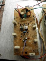
Im reapiring Yamaha EMX3500 power mixer. One channel work OK, other is missing positive part of signal. I resoldered every joint, replaced small signal transistors, measured every part I can but I cant figure out whats causing that kind of signal.
Attachments
Last edited:
One channel work OK, other is missing positive part of signal.
The supply voltages are normal and shared by both channels?
What is the DC output offset voltage?
> replaced small signal transistors
Half-output like that can certainly be LARGE-signal transistors.
Half-output like that can certainly be LARGE-signal transistors.
Supply was externally, most of voltages are ok if compared to good channel just base voltages are fluctuating on bad module. But I cannot find out why..
Im reapiring Yamaha EMX3500 power mixer. One channel work OK, other is missing positive part of signal. I resoldered every joint, replaced small signal transistors, measured every part I can but I cant figure out whats causing that kind of signal.
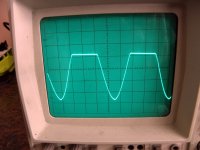
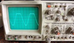
The signal isn't missing any part of the signal. You got your oscilloscope in AC mode, which is for filteriing out DC only. The positive half wave is missing so the capacitor is 'evening it out'. Go to DC and your measurement will show up correctly.
If you are measuring an amplifier output, you practically always need DC measuring. Not only does this avoid such misleading readings, you immediately see if there's any DC offset.
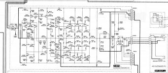
When comparing both channels I found that good one has -1.12V at collector Q207, bad has the same, but not stable, at collector Q206 good has +1,12V, bad has around +0,8V and changing up and down (+-0,1V).
I replaced R216, R217, PO201, VR201, D208, but problem persists.
With output devices removed theres no difference.
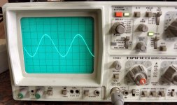
At output using probe 10:1 and DC mode I get this.
I replaced R216, R217, PO201, VR201, D208, but problem persists.
With output devices removed theres no difference.
At output using probe 10:1 and DC mode I get this.
Attachments
1) start by checking +V and +V rails, post values here
2) test amplifier with output transistors but with and without load, post results.
It might produce full wave without load but lose top half loaded, meaning it can´t supply current to the load.
Or it might plain not have the voltage drive also, that´s why we need all tests, to imagine and confirm or discard hypothesis.
3) you might have all 3 Q213/217/221 open or all 3 emitter resistors R236/242/265 or open driver transistor Q211 or tracks leading to respective bases might be open.
4) measure Vbe and Vce at Q213/217/221/211.
We expect around 0.5Vce and almost full +V as Vce
5) Q209 might be shorted so continuously clamping positive halof of signal.
So now you have your homework 😉 , do it and post results 🙂
Thanks JMFahey!
1) As I said I'm using lab supply for testing, so +V and -V rails are +70V and -70V.
2) All tests are done without load on both modules so it shouldnt be current related.
3) Positive Q213/217/221 are good, all emitter resistors too. My sine output is normal to about at +45V when positive wave becomes cut, negative goes normal near supply voltage (as it should)
4) Vbe at Q213/217/221 is 0,47V, at 211 is 0,53V. Vce is near supply voltage (70,0V and 69,6V)
5) To be sure Q209 isnt clamping the signal, I replaced R224, R225, D210, D211, R230 and R231. Once again I resoldered every joint on board just to be sure.
I have figured out something. If I freeze 1N4148 diode D206 and D207 my signal becomes normal if I reheat them problem becomes worse. I measured cca 0.3V difference between hot and cold and I add another diode in series.
After that problem dissapears. I have replaced all diodes and resistors in this section so what is causing this?
Best regards
After that problem dissapears. I have replaced all diodes and resistors in this section so what is causing this?
Best regards
Attachments
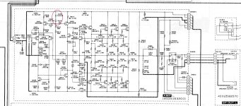
Those diodes set the DC (bias) current through Q205/207/208. That means they also set the maximum amount of base current that can be fed to Q211....I add another diode in series.After that problem disapears.
<snip>
what is causing this?
So what has happened is that Q211 (in the defective channel) now needs much more base current than it used to.
This is a clear indication that something is wrong with the area around those four NPN transistors that supply the positive half-cycles of output current - Q211, Q213, Q217,Q221. At least one of those four transistors is not pulling it's weight. It could be the driver itself, Q211, has failed, or it could be that some or all of the output NPN devices are not able to supply their share of the output current.
Check Q211, Q213, Q217, Q221, their emitter resistors, base resistors, PCB traces in that area. Look for dead semiconductors, burned resistors, bad solder joints, cracks or burns in PCB traces, something that is keeping those four NPN output transistors from doing their job of supplying current to the loudspeaker.
When you find that something, you will probably have fixed the problem.
By the way, your extra diode "fix" is going to put more strain on Q205 and Q207. It is not the right fix. When you find out and fix the real problem (most likely centered on those four NPN transistors), I highly recommend removing that extra diode.
-Gnobuddy
- Status
- Not open for further replies.
- Home
- Live Sound
- Instruments and Amps
- Yamaha EMX3500 power mixer problem - need help