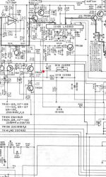
So from what you say R228 actually does go somewhere else. So you need to see what that extra 'input' to TR135 is for and why it takes the base high and puts it into mute.
Is there a missing blob here although I wouldn't then expect the IC to be linked to that point as well... but you never know:
Is there a missing blob here although I wouldn't then expect the IC to be linked to that point as well... but you never know:
Attachments
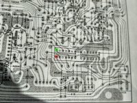
Hi, that is a possibility that its connected to the ic, but first I must figure out how this switch works, or is supposed to work anyway, the location I disconnected is marked in red, i presume with the switch at a certain setting it jumps it over to the area marked in green, or am I wrong? I will do some testing with the continuity tester later tonight. I have given the contacts inside the switch a clean with some switch cleaner and ear bud, the contacts I could reach anyway (open at the back) and they were fairly dirty, I had blown in some switch cleaner before.
Attachments
Its very difficult working from images and pictures without actually having the thing in front of you 🙂
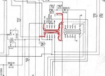
You will have to trace the line all the way back and see which switch contacts are closed. Looking at the circuit and it seems that it does connect as you show but that is only because that switch has the two poles in parallel. The other one looks different.
You will have to trace the line all the way back and see which switch contacts are closed. Looking at the circuit and it seems that it does connect as you show but that is only because that switch has the two poles in parallel. The other one looks different.
Attachments
"Its very difficult working from images and pictures without actually having the thing in front of you " even with it in front for me 🙂 Ok that makes more sense so it does not connect the pin directly across from it then. I will have to leave it for a few days again as I have to go to my real job for the next few days, but at least we are getting somewhere with it. I will do some continuity testing to see if the pins are connecting in the switch. Thanks a lot for your help again.
As drawn the switch does have the effect of connecting the pins opposite to each other but that is because the right hand terminals on that diagram are connected together. It doesn't just connect them together, it puts 12 volts on them as well.
So in the position shown the switch seems to be putting 12 volts on the upper and lower left hand pins. If the switch is moved one position to the right then the 12 volts is removed from those end pins and the circuitry connected to each individual pin takes over.
It's not easy to figure out but that is it seems to be drawn to me but you check it for real by measuring 🙂
Ah yes I see now what you mean, I will update in a few days if I find anything else of interest, there is always an option to leave c170 disconnected, ok the FM muting pot will not work, does anyone actually ever use it anyway, is that not what the volume control is for !! This is why I love my JVC R-S7 no million switches on it at least, and sounds decent too.🙂
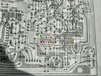
Had another look at this, and the green and red squares I had marked do not have continuity to any other pin on the switch (Switch removed), Likewise the other block to the right does not connect any pins with the rotary switch at any setting. The connections that are made are marked. I de-soldered the switch and without dismantling it I sprayed it with servisol super 10 again, and cleaned the contacts that I could reach with cotton ear buds. No joy. The strange thing is if I unsolder R228 at the switch end I get my -11 volts approx (if the switch is supposed to pull +12 and -11.6 together) to this pin would that fix it, this would bring +12V to the base of TR135) . which is expected as you mention. I forgot to check if the pin is shorted to ground, I will check that later. I did notice that the slider mechanism on the switch does not look like it goes back far enough to reach the last pin, maybe someone already dismantled it and its out of alignment. There are some clips on the bottom of the switch holding the PCB in place That I could pry open, but there is also something that looks like a rivet, which I am not sure if its holding the PCB or not.
Attachments
Last edited:
So do you think the switches might be faulty? You should be able to measure reliable continuity between the common pin of the switch and the other pins.
Providing it doesn't cause other issues then overriding the mute voltages and applying a negative 12v is perhaps an acceptable solution to get it working.
As I think I mentioned earlier, its very difficult to get a handle on this from just the diagrams and layout... you need it in front of you to see how it all comes together operationally.
Yes looks like the switch as I un-soldered it and only the connection I have marked with the different colors are working I wanted to re-solder the pads and give it a good clean. Think best option other than dismantling the switch and trying to re-align the sliding mechanism is to just leave the capacitor removed so the signal is not pulled to ground through TR135 at this stage. Thanks for your help with this, it was a fairly time consuming one.
- Home
- Amplifiers
- Solid State
- Yamaha cr-3020