Hello everyone,
I was wondering if anyone could help me understand some of these TD and D class schematics.
I'm trying to fix a Yamaha P7000 that had a few components fried and I'm slowly getting the schematics only for one bit that I don't understand.
For what I understood class TD means the V+ and V- supply rails are tracking the input signal keeping the Vce of the push pull transistors at minimum, minimizing heat losses. That tracking supply voltage is supposedly being controlled via PWM.
In the Yamaha case I can locate the mosfets that drive the power supply rails, though I was expecting to find a pwm circuit driving the gate but I can't?
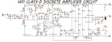
Also in this other generic ClassD amp schematic I can locate the comparator stage but I can't locate the high frequency oscillator to create the PWM signal.
Thanks in advance for any help. I've been trying to research online but as for discreet ClassD designs I couldn't find much info.
Yamaha p7000 service manual+schematics
YAMAHA P5000S P7000S SM 1 Service Manual download, schematics, eeprom, repair info for electronics experts
Cheers,
Alex
I was wondering if anyone could help me understand some of these TD and D class schematics.
I'm trying to fix a Yamaha P7000 that had a few components fried and I'm slowly getting the schematics only for one bit that I don't understand.
For what I understood class TD means the V+ and V- supply rails are tracking the input signal keeping the Vce of the push pull transistors at minimum, minimizing heat losses. That tracking supply voltage is supposedly being controlled via PWM.
In the Yamaha case I can locate the mosfets that drive the power supply rails, though I was expecting to find a pwm circuit driving the gate but I can't?
Also in this other generic ClassD amp schematic I can locate the comparator stage but I can't locate the high frequency oscillator to create the PWM signal.
Thanks in advance for any help. I've been trying to research online but as for discreet ClassD designs I couldn't find much info.
Yamaha p7000 service manual+schematics
YAMAHA P5000S P7000S SM 1 Service Manual download, schematics, eeprom, repair info for electronics experts
Cheers,
Alex