You might try 1N5819 Shottky diodes.
https://www.digikey.com/en/products/detail/stmicroelectronics/1N5819/1037326
https://www.digikey.com/en/products/detail/stmicroelectronics/1N5819/1037326
Today I used the amp with the 2x 1N4148 version: stone cold, voltage pin1 to pin6 is 108V, pin1 to pin5 is 50.1V, idle current at 5 mV and rising. I plugged a bass guitar right into it. It sounded distorted, with any setting on the waveform trimmer.
Then I put in again the 3x 1N4148 "varistor" (boiling hot, voltage pin1 to pin6 is 89.4V, pin1 to pin5 is 42.6V, idle current 200mA. This time my bass sounds about right, kind of mellow, really interesting.
So I have to figure out the right configuration for the varistor. Or I could modify resistor 820K and 470K trimmer to get the center voltage right, and/or the 470R resistor and 470R trimmer (both in parallel) to get the correct idle voltage.
I could also put 2 mega extraction fans at the heatsink but the ones I have on hand are quite noisy...
I'm concerned that your amp may be oscillating:
I note that there have been many substitutions of transistor types, possibly provoking oscillatorion. Further, some of the reported base to emitter voltages seem way too large to for non-Darlington transistors. Eg. the Vbe of TR309 appears to be 1.3V (52.9V-51.6V); the TR303, TR304 differential pair seems to show TR304 is cutoff re TR303--- which would prevent the amp output from biasing to ~50% of B+. You might try to probe directly across the b-e junctions for confirmation.
Can you get a peek from someone having a scope?
3x 1N4248 version: Vbe of TR309 (TIP31A) measures 0.52V, for TR303 its 0.572V and TR304 its 0.605V
2x 1N4148: for TR309 it is 0.582V, TR303 its 0.624V and TR304 its 0.527V
2x 1N4148: for TR309 it is 0.582V, TR303 its 0.624V and TR304 its 0.527V
Well, that's encouraging. You might measure base-to-base offset voltage of TR303, TR304. Ideally, it would be 0mV, but could be tens of mV.
If that looks good, it reduces suspicion of oscillation. Later, I'll suggest some bias trimmer tweak experiments to see if they respond rationally.
I'd still get a few of the Schottky diodes for experimentation. How how are you thermally attaching the diodes? Even if you achieve good coupling and enough compensation to stabilize bias current, there could be a temporary temperature spike until the sensing diodes settle to the elevated heatsink temperature.
Well, offset voltage between base of TR303 and TR304 with 2x 1N4148 version is 40V, 3x 1N4148 version it is 24V.
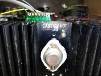
These 1N4148 diodes are attached directly to the heatsink by a metal clamp. The stock STV-3H diode was screwed to the sink.
I use a small piece of heat resistant hose to isolate the exposed solder joints between each diode.
I also installed a switch to easily select between the 2 diode and 3 diode version. I'm not sure if this has any influence on the diodes behavior...
40V between bases! Something is way wrong.
I suggest connecting one DVM from amp output and ground via clip leads so that you can monitor voltage. Assuming it’s near 50V, watch for changes while measuring TR303-TR304 base offset voltage. What do you see?
I have to leave for appointment, back later.
I suggest connecting one DVM from amp output and ground via clip leads so that you can monitor voltage. Assuming it’s near 50V, watch for changes while measuring TR303-TR304 base offset voltage. What do you see?
I have to leave for appointment, back later.
2 diode varistor: Speaker offset voltage is around 0.028mV, base to base offset on TR303 and TR304 is about 44.1V, slowly decreasing.
3 diode varistor: Speaker offset voltage is around 0.005mV, base to base offset on TR303 and TR304 is about 24V, also slowly decreasing.
The heatsink gets hot really fast with 3 diode varistor, and I have to put is component side up in order to touch the base leads with the probes and not make a short ...
"Speaker offset voltage is around 0.005mV." I'm not sure how to interpret "Speaker offset voltage". I would expect the amp output voltage to be about 50% of the B+--- that is somewhere around 50V re pin1. Is the output nearly 0V? Would you elaborate how this is being measured?
I'm concerned about the many volts between bases of TR303-TR304. Likely it means failure of one or both devices, but data in post #9 indicated about 50V at output. Has something changed/failed in the interim? Maybe it's time to remeasure post # 9 test nodes. BTW, I would opt for the two-1N4148 diode configuration until things are more stable.
Thanks.
Copied from Mrs and Mr Google:
"DC offset voltage in a power amplifier refers to a DC voltage present at the output, even when no signal is input, which can cause issues like speaker damage or distortion. Ideally, this should be zero, but a small amount is often acceptable. "
"DC offset voltage in a power amplifier refers to a DC voltage present at the output, even when no signal is input, which can cause issues like speaker damage or distortion. Ideally, this should be zero, but a small amount is often acceptable. "
Thanks. This amp is biased mid B+, and thus the large 2200uF cap in series to the speaker. When I inquired about output, I was asking about bias on the output stage, i.e. junction of the two 0.22R resistors. Sorry for any confusion. I wish the schematic included reference designations.
So what bias voltage do you observe?
Thanks.
So what bias voltage do you observe?
Thanks.
Would that be between board pin1 (ground) and pin5 (output)?
If so, its 50.1V
Well, there is no such reference ID. This service manual is in the Yamaha style of the olden days...
On the last page of the manual is an illustration with position and value of each component on the board but without component ID. Then, on the previous page is the schematic diagram, also with out comp. ID. It just takes some time to get it right. Also, back in 1980 there was no internet nor scanners for this matter, so it is in black and white, made on a huge copy machine. I remember the days when we all used facsimiles...
On the actual board, there ID numbers for all components, and value for resistors and caps printed on it.
I have a service manuals for a Yamaha TA-60 amplifier from 1969 that also was made in black and white, and there are values crossed by thick black lines, so it is not easy to get correct value.
50V at the output is encouraging.
From post #28: "base to base offset on TR303 and TR304 is about 44.1"
But from post #9:
TR303 base to gnd: 102V
TR303 collector to gnd: 52.1V
TR304 base to gnd: 103V
This data indicates differential input offset of ~1V, i.e. 103V-102V. Wildly different numbers, maybe incorrect measurement probing, but maybe suggestive of oscillation. But the differential stages almost have to work for the output to properly bias to 50V. That dilemma led me to suggest the experiment in #29.
I suggest a different experiment that is less tedious. Note the AC gain is (1+1.8M/10k) = 181. DC bias gain to offset trim is (1+1.8M/100k) = 19. (Unusual that DC gain isn't 1.0). So connect a voltmeter's red lead to board terminal 5 and black lead to gate of TR301. The displayed voltage should be respond to adjusting the 4.7k pot, and I believe you should be able to adjust the voltage the to 0V. Note the initial position of the 470k pot so you can restore. I think it should also perturb the meter reading, but less dramatically. If these experiments behave as described, I'll feel encouraged about the state of the amp.
Assuming the amp behaves as hoped, getting bias current stabilized is the next challenge.
Hm... Post #9 was made with 3 diodes as varistor, post #28 was made with 2 diodes.
I will try to get this experiment done tomorrow.
I already moved all pots 470R / 4.7K / 470K on the board a gazillion times... No way I can possibly remember the original settings...
I will try to get this experiment done tomorrow.
I already moved all pots 470R / 4.7K / 470K on the board a gazillion times... No way I can possibly remember the original settings...
4.7k wave pot gets down to 2.78v full clockwise and 7.1v full ccw.
470R idle pot, I can set it at 5mV
and 470k center voltage gets down to 54.5V at pin5 to pin1, which is half of pin6 to pin1 109.5 VDC
Output sound quality however is not optimal at all.
470R idle pot, I can set it at 5mV
and 470k center voltage gets down to 54.5V at pin5 to pin1, which is half of pin6 to pin1 109.5 VDC
Output sound quality however is not optimal at all.
- Home
- Amplifiers
- Solid State
- Yamaha B100-115ii hot heatsink