The negative lead of your meter goes onto a clean ground point which would normally include chassis. You can also use the ground side of the RCA input sockets or there might be a separate turntable ground screw connection.
You then measure the signal voltage (which must be from a test tone, not music) to those resistors.
The preamp is passive which means you can begin by checking this with the amp turned OFF. The signal should be measurable all the way up to the power amp input. That will give you an idea of levels as you alter the volume control and so on.
Begin by checking the signal level on the input sockets and then follow it through the amp. You should be aiming for at least a few hundred millivolts of signal at the sockets, exactly how much depends on what you playing the tone on. Remember to set your meter on AC volts for this.
After having the amp sat on a table for three months I finally got round to trying to make some progress and carry out these tests.
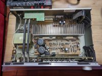
Despte a number of attempts and a good couple of hours looking at the board and service manual scematics I struggled to locate any relevant components on the circuit board, other than transistors Q137 and Q138.
Having read the circuit diagram a bit more I then decided that if I could identify the terminals on the transistors, I should be able to see what voltage was present on one of the terminals which is connected back to R113 / R114. After a trip back to school, (well internet school) I identified that the transistors are NPN in a bce configuration.
After connecting a headphone socket > stereo phono cable from my laptop to the CD input I observed the following values: at different rotations of the volume control, results in millivolts AC measured at what I believe is the emitter
Channel......Left...Right
Defeat....... 3........3
Pos 1........25......26
Pos 2........104.....102
Pos 3........664......669
Full...........791......771
The full volume reading almost corresponds to the voltage I measured at the phono connections, there's a loss of about 20-25 mV through the circuit on both channels
I think these readings are "normal", so the issue is later in the circuit ?
... just trying to pick this up from where you last left off......
So those AC voltages seem pretty equal. Have you measured the before and after voltages at the speaker relay?
So those AC voltages seem pretty equal. Have you measured the before and after voltages at the speaker relay?
... just trying to pick this up from where you last left off......
Yeah, sorry about that 😱 , I remembered I had an old Yamaha receiver I bought in the US with a 240 >110v transformer and so that has been deployed in the workshop, meaning the pressure to fix this one eased off, necessity being the mother of invention, or repair, and all that.
I will start studying the schematics again to find the speaker relays and repeat the test. I can't look physically for now as I'm no longer with the amp.
Thanks 🙂

I hope you managed to fix your amplifier, it is exactly 5 years from the last message in this thread 😉
I am seeking comments on feasibility and whether it would be worthwhile on my intended modding project.
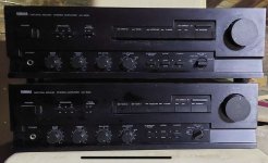
I just bought two AX500 (how fortunate am I that a seller was selling the pair, and I needed a pair for bi-amping) as a stop gap measure, so that I do not have to rush to finish my Aleph projects (no mistake on the plural form)
I wonder if I could make a quick mod by making it a dual mono, i.e. transferring the transformer and related PSU components of one to the other (physically or through wire) such that each transformer serves one channel in a stereo amplifier. I have not received the amplifiers yet, but I think the transformer secondary voltage is 28~30V, judging from its power output of 85W@8 Ohm.
The specs says that the amplifier consumes 430W (EU version, I think the US version is 370W), so its transformer should be rated for at least 430VA? So having 430VA per channel for 85W amp should be plentiful, hopefully in addition to the 85W@8 ohm, it will also do continuous 340W@2 ohm😉 but…
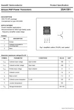
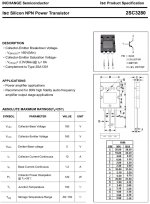
A question on the output power transistor, a 2SC3280 (or 2SD1718A) and 2SA1301 (or 2SB1163A) , the max. collector current is 12A, and max. collector dissipation is 120W.
85W@8 Ohm output would translate to 26Vrms at the speakers, ==> 3.25A. max. collector current of 12A should allow it to drive speaker > 4 Ohm ==> 6.5A, and may be dynamically into 340W@2 ohm? Would it be stressing the poor power transistor too much? No. I don’t intend to add additional power transistors to the output stage, this mod should be relatively effortless as a stop gap solution only, until the Aleph is up and running.
For the remaining amplifier that donated its transformer for the betterment of amplifier kind 🤣 it will be powered by the +-38V PSU from my Aleph Project in the interim.
All comments, good or otherwise, are welcome. Thank you!
Have a pleasant weekend!
I am seeking comments on feasibility and whether it would be worthwhile on my intended modding project.
I just bought two AX500 (how fortunate am I that a seller was selling the pair, and I needed a pair for bi-amping) as a stop gap measure, so that I do not have to rush to finish my Aleph projects (no mistake on the plural form)
I wonder if I could make a quick mod by making it a dual mono, i.e. transferring the transformer and related PSU components of one to the other (physically or through wire) such that each transformer serves one channel in a stereo amplifier. I have not received the amplifiers yet, but I think the transformer secondary voltage is 28~30V, judging from its power output of 85W@8 Ohm.
The specs says that the amplifier consumes 430W (EU version, I think the US version is 370W), so its transformer should be rated for at least 430VA? So having 430VA per channel for 85W amp should be plentiful, hopefully in addition to the 85W@8 ohm, it will also do continuous 340W@2 ohm😉 but…
A question on the output power transistor, a 2SC3280 (or 2SD1718A) and 2SA1301 (or 2SB1163A) , the max. collector current is 12A, and max. collector dissipation is 120W.
85W@8 Ohm output would translate to 26Vrms at the speakers, ==> 3.25A. max. collector current of 12A should allow it to drive speaker > 4 Ohm ==> 6.5A, and may be dynamically into 340W@2 ohm? Would it be stressing the poor power transistor too much? No. I don’t intend to add additional power transistors to the output stage, this mod should be relatively effortless as a stop gap solution only, until the Aleph is up and running.
For the remaining amplifier that donated its transformer for the betterment of amplifier kind 🤣 it will be powered by the +-38V PSU from my Aleph Project in the interim.
All comments, good or otherwise, are welcome. Thank you!
Have a pleasant weekend!
Attachments
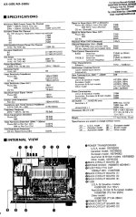
I have the same AX-500 model but for European market, the power consumption is 430W, but Asia variant of the same model is 220W.
The specs for Asia variant is the same as European variant, I.e. 85W@8 ohm, 230W@2 ohm.
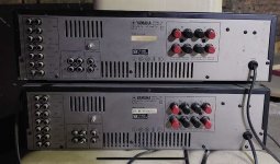
The transformer are different. Different VA rating?
How does one make 2 variants of the same amplifier with different power consumption but have the same power output?
Lower biasing voltage for Asia variant?
The specs for Asia variant is the same as European variant, I.e. 85W@8 ohm, 230W@2 ohm.
The transformer are different. Different VA rating?
How does one make 2 variants of the same amplifier with different power consumption but have the same power output?
Lower biasing voltage for Asia variant?