yamaha ax-400 input stage help +mods
Hello good people.
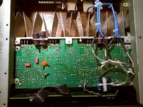
I got a salvaged Yamaha AX-400 that i repaired and tinkered with lots of mods and experiences done to it: salvaged much bigger Technics OFC transformer (DC rails from 56v original to 50v with the technics but much more current available); bigger 10.000uf CDE SLPX psu caps; bigger 10A rectifier, original was 6A; full recap with CD, Rubycon and Nippon Chemi-Con; input LTP bootstrapping cap removed (personal preference in listening tests); vbe bypass caps changed to Panasonic FC 18uf;added local psu bypass on input stage with Panasonic FC 100uf and 47nf MKT near load(to dirty ground) and local psu bypass on both rails, right near the output transistors, for both channels, with 1000uf 63v El-caps, full bypass/removal of preamp controls:tone,loudness,balance; PSU filter caps after Zener regulator changed to 1000uf; removal of phono stage pcb (now in separate box with separate psu); input and only caps on signal path changed to polyester orange Philips 4,7uf; speaker terminal wiring completely re-done with quality wiring (flex and solid) straight from the output relay to new boards with the output resistor/coil combo(resistor on the downside of the pcb) as the original wiring scheme was a joke; new better matched LTP 2sa970bl transistors (reduced dc offset by 50%) joined/coupled with thermal compound and heat shrink tubing; new bourns muti-turn bias pot with bias tuning(original ones were shot); new 10A speaker relay with better contact quality, instead of original 4A which was all blackened; input ceramic caps on rca plugs replaced with 33pf np0/c0g (this yamaha used strangely high values here that damaged 20khz response), original binding posts were shot (no screw and corroded) and were removed; 3M heavy rubber glued to chassis for transformer vibration dampening; all contacts thoroughly cleaned; all thin aluminum pcb jumpers in the high current supply and signal paths changed to 1.02mm copper; feedback electrolytics Panasonic FM 220uf 25v bypassed with Wima MKS02 1uf; C141 and C142 changed to polyester; -16v line and regulation/filtering components removed from the board as it was no longer needed without RIAA phono input opamps; several critical resistors upgraded to 1% metal film; white power-on LED supplied from extra 10v winding from the technics transformer and led supply circuit removed from main board, holes covered with body filler and white painting on front panel😀
You bet it sounds like it should.
Some of you might be critical of lesser mods in lesser machines but i can tell you it has been a great ride, mainly learning a lot in the process, turning a mediocre amp into a less mediocre amp and training for future projects. All mods and improvements were tracked/logged with RMAA readings (nice soundcard, all parameters equal) and while some produced very good measurement results, others mods produced clearly audible results only heard with dynamic content like music (like the much bigger technics transformer).
In the end noise down by 14db, thd down by 10db, crosstalk from -63 to -77, ruler flat frequency response instead of skewed original one, stronger bass and transient response, wider and defined stage, buzz noise in speakers disappeared (50hz harmonics cleaned), almost dead silent with ears against the drivers.
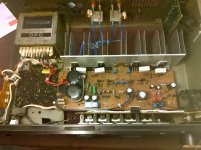
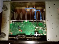
I attached some pictures of the mods.
I will keep this post (#1) updated as i can only edit this one overtime.

BUT the real reason i started this thread was to ask advice about further mods to the circuit, particularly to the input stage, as it seems to me that this amp has a very decent VAS and output stages. i'm not afraid to do crazy things like daughter boards and such. I built mic preamps and power supplies with great success before but i'm kind of a newbie in the power amp world.
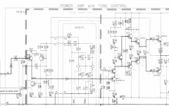
I attached the schematic picture.
thank you very much for the help you been giving me already with this machine and thank you in advance for suggestions.
Hello good people.
I got a salvaged Yamaha AX-400 that i repaired and tinkered with lots of mods and experiences done to it: salvaged much bigger Technics OFC transformer (DC rails from 56v original to 50v with the technics but much more current available); bigger 10.000uf CDE SLPX psu caps; bigger 10A rectifier, original was 6A; full recap with CD, Rubycon and Nippon Chemi-Con; input LTP bootstrapping cap removed (personal preference in listening tests); vbe bypass caps changed to Panasonic FC 18uf;added local psu bypass on input stage with Panasonic FC 100uf and 47nf MKT near load(to dirty ground) and local psu bypass on both rails, right near the output transistors, for both channels, with 1000uf 63v El-caps, full bypass/removal of preamp controls:tone,loudness,balance; PSU filter caps after Zener regulator changed to 1000uf; removal of phono stage pcb (now in separate box with separate psu); input and only caps on signal path changed to polyester orange Philips 4,7uf; speaker terminal wiring completely re-done with quality wiring (flex and solid) straight from the output relay to new boards with the output resistor/coil combo(resistor on the downside of the pcb) as the original wiring scheme was a joke; new better matched LTP 2sa970bl transistors (reduced dc offset by 50%) joined/coupled with thermal compound and heat shrink tubing; new bourns muti-turn bias pot with bias tuning(original ones were shot); new 10A speaker relay with better contact quality, instead of original 4A which was all blackened; input ceramic caps on rca plugs replaced with 33pf np0/c0g (this yamaha used strangely high values here that damaged 20khz response), original binding posts were shot (no screw and corroded) and were removed; 3M heavy rubber glued to chassis for transformer vibration dampening; all contacts thoroughly cleaned; all thin aluminum pcb jumpers in the high current supply and signal paths changed to 1.02mm copper; feedback electrolytics Panasonic FM 220uf 25v bypassed with Wima MKS02 1uf; C141 and C142 changed to polyester; -16v line and regulation/filtering components removed from the board as it was no longer needed without RIAA phono input opamps; several critical resistors upgraded to 1% metal film; white power-on LED supplied from extra 10v winding from the technics transformer and led supply circuit removed from main board, holes covered with body filler and white painting on front panel😀
You bet it sounds like it should.
Some of you might be critical of lesser mods in lesser machines but i can tell you it has been a great ride, mainly learning a lot in the process, turning a mediocre amp into a less mediocre amp and training for future projects. All mods and improvements were tracked/logged with RMAA readings (nice soundcard, all parameters equal) and while some produced very good measurement results, others mods produced clearly audible results only heard with dynamic content like music (like the much bigger technics transformer).
In the end noise down by 14db, thd down by 10db, crosstalk from -63 to -77, ruler flat frequency response instead of skewed original one, stronger bass and transient response, wider and defined stage, buzz noise in speakers disappeared (50hz harmonics cleaned), almost dead silent with ears against the drivers.
I attached some pictures of the mods.
I will keep this post (#1) updated as i can only edit this one overtime.
BUT the real reason i started this thread was to ask advice about further mods to the circuit, particularly to the input stage, as it seems to me that this amp has a very decent VAS and output stages. i'm not afraid to do crazy things like daughter boards and such. I built mic preamps and power supplies with great success before but i'm kind of a newbie in the power amp world.
I attached the schematic picture.
thank you very much for the help you been giving me already with this machine and thank you in advance for suggestions.
Attachments

Last edited:
I now swapped the fake 2sc3182 and 2sa1265 (yes i cracked them open and compared the die with the burnt originals) i was using, after i repaired the burnt channels, for authentic Toshiba 2sa1302 and 2sc3281 from a wrecked old Crest PA amp. The Crest had several burnt output transistors but the majority were tested good and i now have a nice stash of 1302's and 3281's for future diy projects. Bias was of course, re-tuned and is more stable than before it stays at desired value almost all the time with little to none drifting.
I also swapped the tiny aluminum pcb jumpers in the high current power and signal paths with 1.02mm copper wire and relocated vbe transistor for right channel, with longer legs nearer to corresponding output device.
Also did mods to the grounding scheme and disconnected input jack and chassi connection ground from the input stage signal and feedback network ground, instead i connected them to ground plane joining the two big smoothing caps.
I'm still looking for suggestions of mods/upgrades to the original circuit.
An externally hosted image should be here but it was not working when we last tested it.
Attachments

Last edited:
The NBF shunt capacitor C139 and C163 could be bypassed with lower value film cap...and/or ceramic...and/or polystyrene......I'm still looking for suggestions of mods/upgrades to the original circuit.
Another thought is to replace the polarised C139 with NP/BP plus lower value shunts.
Read up on Quasimodo thread and apply damping to the power TX secondaries.
You can have some fun with amps like these.
Dan.
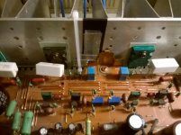
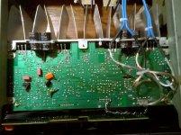
Added local psu bypassing for each rail in each channel, near the point of load, with 680uf 63v x 4.
Previous input stage psu bypass scheme changed to ceramic x7r's near point of load.
Previous input stage psu bypass scheme changed to ceramic x7r's near point of load.
An externally hosted image should be here but it was not working when we last tested it.
Attachments
The NBF shunt capacitor C139 and C163 could be bypassed with lower value film cap...and/or ceramic...and/or polystyrene.
Another thought is to replace the polarised C139 with NP/BP plus lower value shunts.
Read up on Quasimodo thread and apply damping to the power TX secondaries.
You can have some fun with amps like these.
Dan.
C139 is bypassed with WIMA 1uf MKS02 and C163 is 3,3uf film.
updates
Output devices bypassed with 1000uf 63v instead of 680uf.
Feedback main gain setting resistor (49kohm) and bypass 10pf capacitor relocated and feedback lines drastically made shorter to near LTP input stage instead of traveling 20cms to the (now defunt) tone control panel connector.
Signal lines from volume control made much shorter to LTP input stage and no more -16v, +16v and led power lines around the preamp pcb.
The photo shows x7r ceramics as bypasses but those were rated at 50v dc and dangerously working at 50v measured dc. So they were swapped to 47nf MKT 100v because they were what i got in the stash.
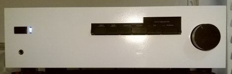
Front panel turned out ok with some aluminum body fill, sanding and spray paint.
Output devices bypassed with 1000uf 63v instead of 680uf.
Feedback main gain setting resistor (49kohm) and bypass 10pf capacitor relocated and feedback lines drastically made shorter to near LTP input stage instead of traveling 20cms to the (now defunt) tone control panel connector.
Signal lines from volume control made much shorter to LTP input stage and no more -16v, +16v and led power lines around the preamp pcb.
The photo shows x7r ceramics as bypasses but those were rated at 50v dc and dangerously working at 50v measured dc. So they were swapped to 47nf MKT 100v because they were what i got in the stash.
Front panel turned out ok with some aluminum body fill, sanding and spray paint.
Attachments
Last edited:
(yes i cracked them open
Not sure how wise it is opening them up.
There are hazardous elements in them.
I certainly wouldn't using any power tools on them as that can cause hazardous dust to be breathed in.
- Status
- Not open for further replies.
- Home
- Amplifiers
- Solid State
- yamaha ax-400 input stage