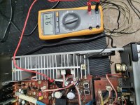
Good evening everyone ! I have this Yamaha amplifier that does not deliver an output signal and when I turn on the relay does not activate! I have replaced all the electrolytic capacitors and measuring with the tester on the 2 pins TP4 and TP3 I have 9mv! Do you know anything about it?
Attachments
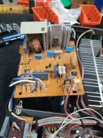
Measure DC voltage between TP2 and chassis/GND. Repeat for TP4 and GND. TP's are the bias TP's on the power amp stage.
Are you measuring the 30Vac between the Grey and white wires?
Are you measuring the 30Vac between the Grey and white wires?

Do you have the schematic?
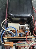
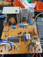
The amplifier have a "X-power" module. It's work like a triac light dimer but in this case it has feedback with an optocoupler.
The amplifier have a "X-power" module. It's work like a triac light dimer but in this case it has feedback with an optocoupler.
yes I found the schematic! I check the control part of the transformer. In this case, to do a test, could I connect the transformer directly to the mains or in this case the triac does not send the voltage to the transformer due to a possible problem?
NOOO!!
The transformer are made for 140V-160V for models that work @ 220V (60-70V for 110V models).
I will recommend also to disconnect the load to to not overvoltage the amplifier. Personally I will made the tests completely outside of amplifier.
You can use a regulable autotransformer to supply directly the transformer BUT I do not see the reason for this test.
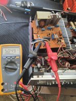
Hello everyone ! I did a test by disassembling the transformer and feeding it with a variac I saw that with an input voltage of 100v I have an output voltage from the transformer of 25v dual but with a high and constant input current of about 1.5A!
Is it possible that I have this anomalous operation due to the fact that I have removed the control board with the SCR?If I replace the transformer with another transformer that supplies me with the right voltage, do I risk damaging something?
Is it possible that I have this anomalous operation due to the fact that I have removed the control board with the SCR?If I replace the transformer with another transformer that supplies me with the right voltage, do I risk damaging something?
If you're saying that the secondary is 25 volts AC (not DC) UNloaded, unconnected, then the high primary winding current is due to a possible shorted turn in its windings.Hello everyone ! I did a test by disassembling the transformer and feeding it with a variac I saw that with an input voltage of 100v I have an output voltage from the transformer of 25v dual but with a high and constant input current of about 1.5A!
Is it possible that I have this anomalous operation due to the fact that I have removed the control board with the SCR?If I replace the transformer with another transformer that supplies me with the right voltage, do I risk damaging something?
A typical transformer should only show around a couple of milliamps current when unloaded.
Of course, I don't know your testing equipment and or its calibrations, or your electronics capabilities.
After all, this is the internet, a not-perfect way to diagnose things in some other place remotely.
What multimeter you use to measure that voltage?
The voltage is not sinusoidal so if you not use a True RMS multimeter the reading are erroneous.
I think that you are not in correct direction.
First of all you have to use an oscilloscope. Measuring with an multimeter, even if it were True RMS, is more or less useless.
The voltage is not sinusoidal so if you not use a True RMS multimeter the reading are erroneous.
I think that you are not in correct direction.
First of all you have to use an oscilloscope. Measuring with an multimeter, even if it were True RMS, is more or less useless.
as a tester I use a Fluke 175 tester! In the AC input of the transformer I used a variac and as a measurement of the absorbed current I used a clamp meter! and I saw that as soon as I get to 100v alternating at the input the current absorbed by the transformer without connecting any load at the output is really too high! I contacted a friend of mine who manufactures transformers and now I will have it analyzed
I have a Yamaha A-6A, Japanese variant of Yamaha A760II witch is little brother of your amplifier. I bought it defective and was the transformer too. I changed the transformer with a toroidal one custom made at a local shop and I gave up at X-power. Now it is a standard transformer power supply. I also change completely the power supply for low level stages. Originally was locally stabilized with zener and power resistors. Now I use a separate secondary from transformers and LM317/LM337 stabilizers set to +/- 15V.
I don't know why the company made such a choice! Isn't a simple transformer simpler and more effective without using triacs or scr?
I can tell from it's design and layout of components, that it's one of those trouble-prone hunks of crap designed by some young idiot fresh out of school.I don't know why the company made such a choice! Isn't a simple transformer simpler and more effective without using triacs or scr?
I've seen other products like that come through the repair shop over the years - they're apparently some part of a "trend" in design.
Just like when VCR's started to use SMPS supplies, and many had power supply issues in the late 1980's/early 90's.

Can you find for tests an adjustable autotransformer?
For all starting test disconnect the transformer from the PCB. If you put at the input of transformer the sinusoidal voltage, starting from 40-60Vac, the output voltage is correct measured being sinusoidale too.
For all starting test disconnect the transformer from the PCB. If you put at the input of transformer the sinusoidal voltage, starting from 40-60Vac, the output voltage is correct measured being sinusoidale too.
I tried powering the transformer with a variac and as I arrive at 90v in input or a constant absorption of 1.5 a in input without connecting loadCan you find for tests an adjustable autotransformer?
For all starting test disconnect the transformer from the PCB. If you put at the input of transformer the sinusoidal voltage, starting from 40-60Vac, the output voltage is correct measured being sinusoidale too.
- Home
- Amplifiers
- Solid State
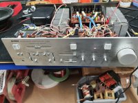
- Yamaha A-960 No audio output