Thanks!
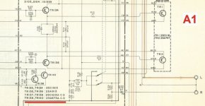
Also, here’s a little more info on the A-1 which can be hard to find, especially the TR137,138,139,140 arrangement and listing in earlier SM’s.
Also, here’s a little more info on the A-1 which can be hard to find, especially the TR137,138,139,140 arrangement and listing in earlier SM’s.
My latest query is.. what would be the best replacements for:
TR525,TR26,TR27,TR28 on the Drive Board.
originals were:
2sa914
2sc1953
TR525,TR26,TR27,TR28 on the Drive Board.
originals were:
2sa914
2sc1953
I have no direct equivalent for those there, we will have to do cross-checking on the net.
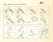
!!!pay attention to the different pinout !!!
2SA914 ⇒ BF416 BF470 BF472
Obsolete Technology Tellye !: TABLE OF 2SA SERIES TRANSISTOR EQUIVALENTS
!!!pay attention to the different pinout !!!
2SA914 ⇒ BF416 BF470 BF472
Obsolete Technology Tellye !: TABLE OF 2SA SERIES TRANSISTOR EQUIVALENTS
how do you do that ?
I can't "cut" this damn diagram in a pdf document :fou:
Thanks for looking up these replacements, much appreciated.
These have also been recommended.
TTC004B,Q (NPN) replaces the 2SC1953
TTA004B,Q (PNP) replaces the 2SA914
Getting closer to reassembling the amp, and hoping it will work when it starts up.
The ‘.’ is only there because it won’t let me post an image without adding some text. But I only wanted to post the images for you.
Can you explain to me how you do to select image windows in a pdf document?
I can't do it and when I find myself with a diagram of this size (that of the yam in the service manual) that I therefore cannot visualize in full, I would like to be able to select pieces of the diagram and extract them from the pdf document
I can't do it and when I find myself with a diagram of this size (that of the yam in the service manual) that I therefore cannot visualize in full, I would like to be able to select pieces of the diagram and extract them from the pdf document
Sorry, I can’t explain.
I have just forwarded individual pages, but individual pages were what I started with.
I have just forwarded individual pages, but individual pages were what I started with.
For adjustment of idle current (TP1-TP3, TP2-TP4 on the Elec Capacitor Board)
Is there another pair of locations from where I can take this reading?
Is there another pair of locations from where I can take this reading?
- Home
- Amplifiers
- Solid State
- Yamaha A-1 idle current issue