Another important point: The pad with the screw-hole of the LM317 is connected to Vout. Either use an insulating washer and an insulating pad for mounting the LM317 to the heatsink, or take great care in ensuring that the heatsink does not touch other parts of the circuit or enclosure.
Hi guys- Well I have had some success. 🙂 One channel is working the other is dead. 🙁
The measurements on the regulator are are a bit low at 4.47v. Between pins 4 and 5 it reads a bit high at 7.68. 😕
I put on a much larger heatsink with an insulating pad and washer. It still gets fairly warm but not so hot that I can't touch it.
Thanks again for all your help 😀
The measurements on the regulator are are a bit low at 4.47v. Between pins 4 and 5 it reads a bit high at 7.68. 😕
I put on a much larger heatsink with an insulating pad and washer. It still gets fairly warm but not so hot that I can't touch it.
Thanks again for all your help 😀
Hi guys- Well I have had some success. 🙂 One channel is working the other is dead. 🙁
The measurements on the regulator are are a bit low at 4.47v. Between pins 4 and 5 it reads a bit high at 7.68. 😕
I put on a much larger heatsink with an insulating pad and washer. It still gets fairly warm but not so hot that I can't touch it.
Thanks again for all your help 😀
You are measuring Vin vs Vout on the regulator, I guess? You're supposed to measure Vout vs GND, which should give you the same 7.68V as you have on the heater pins. These do seem a bit high. You can get this nearer to the 6.3V in the data sheet by either
(a) replacing the 5K resistor with a 4K one,
or if you don't have a 4K part,
(b) putting a 22K resistor in parallel to the 5K one, giving a total resistance of approximately 4K. Important: If you do this, really make
sure you have correctly paralleled the two. If you disconnect the 5K resistor accidentally, leaving only the 22K, you WILL kill your filament. If you make modifications to the regulator circuit, consider desoldering the wire from regulator to heater, making the modification, measuring the voltage again and then reconnecting the heater if the voltage is okay.
Also note that the author of your PDF may well have had a reason to make the heater voltage that high, although I can't think of any.
When you say one channel is dead, are you still talking about the headphones or the actual amp? If it's the amp, I would try replacing the opamp chip, because that one may have taken some damage through that solder blob connection.
Last edited:
It's good to hear you are making progress.
If you are going to get new resistors for the regulator...
Replace the 1k resistor with 243 ohms and the 5K with the 1K.
That will give you 6.4 volts. The resistors don't need to be as large
as the 5k you have. Both can be the same size as the 1K you have now.
Follow the advice as above. Test the heater voltage with the tube removed.
I am going to order a new op amp and regulator for this amp. Also I thought to order new resistors for the regulator. What do you think would be the best ones given that I am getting new ones.
Thanks!
Thanks!
Well I think this guy is doomed 🙁
I replaced the reg and the resistors on it as well as the op. Unfortunately I managed to lift the pad on one of the outputs 😱 I've tried wiring the output onto the pin of R4 but the dc offset of that channel is completely out of whack. I noticed a few pads on this board lifting a bit. Maybe just a poorly made board as well as my less than perfect technique 😱
I might try to build it point to point. Can you use a piece of pvc instead of perfboard as I happen to have a piece the right size at hand and have to drill holes for the tube anyway.
Once again - thanks for all your help. You guys are great 😀
Piece of PVC? No. PVC doesn't like heat at all, it will decompose and melt at soldering temperatures.
Hy guys- Looks like I will need your help again 😱
After a lot of screwing around I have managed to rebuild the amp on perfboard. The power seems ok- aprrox. 12.5 input, 6.5 out at the reg. and 6.5 on the tube. The tube glows and there are no problems indicated with the dim bulb tester. That's the good part 🙂
Unfortunately there is no sound- absolutely nothing 😕 Somewhere in the input or output I've got something wrong but I can't figure out what.
Any advice would be most welcome 🙂
Attachments
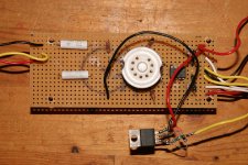

By the way- the regulator is off it's heat sync only for this photo. I have the whole thing mounted on a piece of 3/16 aluminum plate.
cheers
cheers
- Status
- Not open for further replies.
- Home
- Amplifiers
- Headphone Systems
- YAHA HELP