So I have a x604 Amplifier here and It amplifies Left and Right Rear channels just fine. Left Front Channel and Right Front channels are a different story.
When I hook my function generator to Left front there is little amplification (gain set to min, DC 0.00v on all channels) out of the Left Front +- output terminals. But when I look at the Right Front +- output terminals-input still connected to Left Front- I have amplification of Left's input...It seems there is huge "crosstalk" (for lack of better word) between the channels. Is there anything common to this amp that might cause this? I appreciate any help/advice in advance.
When I hook my function generator to Left front there is little amplification (gain set to min, DC 0.00v on all channels) out of the Left Front +- output terminals. But when I look at the Right Front +- output terminals-input still connected to Left Front- I have amplification of Left's input...It seems there is huge "crosstalk" (for lack of better word) between the channels. Is there anything common to this amp that might cause this? I appreciate any help/advice in advance.
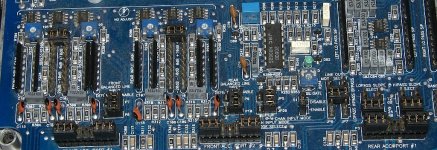
no. Balanced inputs defeated and gain is 0dB. I hope the attached image helps.
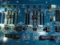
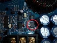
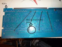
Also in the second image the LM311N (u22) circled, Its waveform on pin 2 and 3 do not match the 311 to the left(u21). they look to be garbage/noise. I looked at your tutorial's waveform of a x603 and u21 matches u22 does not. Thank you again for your help Mr. Babin.
Also in the second image the LM311N (u22) circled, Its waveform on pin 2 and 3 do not match the 311 to the left(u21). they look to be garbage/noise. I looked at your tutorial's waveform of a x603 and u21 matches u22 does not. Thank you again for your help Mr. Babin.
Attachments
no it does not. When I have signal into Left Front input signal is amplified at max on right front and seems to be minimal on left.
Compare the audio signals on the muting transistors (J108s?) at the input to the power amplifier circuit for each of those channels. Is the signal reaching the right front channel significantly greater than the signal reaching the left front channel?
Ok so I did not even make it as far as the muting circuit. In the first image below here is what all of the inputs look like without signal...it measures -1.04dc with no signal.
The second image, was verified before connection, perfectly good sine wave at the input.
So what do you make of this?
The second image, was verified before connection, perfectly good sine wave at the input.
So what do you make of this?
Attachments
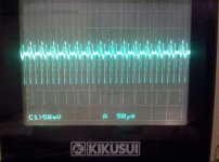
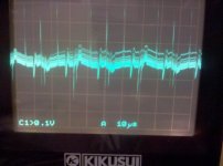
It was taken at 10 kHz. I was working with 1 kHz but must've hit the 10..
so the signal is very weak at the muting transistor for the left channel (the channel I was inputting to) and distorted. The right muting transistor had the signal,while having no direct input, and was also very distorted.
so the signal is very weak at the muting transistor for the left channel (the channel I was inputting to) and distorted. The right muting transistor had the signal,while having no direct input, and was also very distorted.
Sorry its been a few days...life has been at it again.
Okay so I am at 100hz crossovers flat and to answer your question
"Compare the audio signals on the muting transistors (J108s?) at the input to the power amplifier circuit for each of those channels. Is the signal reaching the right front channel significantly greater than the signal reaching the left front channel? "
Yes, the signal is far greater on the right channel than the left.
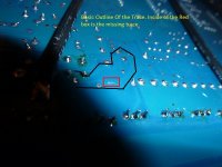
No change after removing muting transistor. Do you happen to have one of these amps? I am curious to find out if a trace I see that is cut on the underside is normal.
I think you'll have to go through the circuit to find the point where the signal drops off. The channels should essentially be identical. At least no you know the problem is in the preamp section and not the power amp.
I don't have one of these. I have photos but only of the top of the board.
I don't have one of these. I have photos but only of the top of the board.
I am not currently in in front of the amp but how likely is it that the 2068 op amps failed. If defective is there a better substitute than the JRCs?
I have a 604X that I can look at the bottom of the board on if that would help. I know the X604 and the 604X are similar I just don't know how similar.
So I have traced the signal to U2 (middle 2068 op amp front channel), and it seems to be my source of headache. When looking at the waveform of "A" output (pin 1) I see DC with just the tops of my input waveform.( ___n___n___ ) That is a rough sketch of the waveform...😉 The non inverting input pin 3 has a poorly shaped version of my input and pin 2 has a similar waveform to 3.
I removed the opamp and found the amplifier behaving normally...or as close to normal as I have seen from it. No crosstalk on the other front channel now and seems to be amplifying the input signal...
So I am curious...and this takes a lot of pride swallowing to ask...how is it with this opamp removed does this beast function? When you move the input sensitivity jumper does it change the amplification through u1 or u2 with the different resistors? It would be far simpler with a schematic i guess..
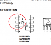
I have attached a pic of the 2068 from the datasheet so others looking can have a visual.
I removed the opamp and found the amplifier behaving normally...or as close to normal as I have seen from it. No crosstalk on the other front channel now and seems to be amplifying the input signal...
So I am curious...and this takes a lot of pride swallowing to ask...how is it with this opamp removed does this beast function? When you move the input sensitivity jumper does it change the amplification through u1 or u2 with the different resistors? It would be far simpler with a schematic i guess..
I have attached a pic of the 2068 from the datasheet so others looking can have a visual.
Attachments
I think that you have to make your own schematic diagram if you want one for an xtant amp.
Which solder pads for the missing 2068 have a clean left channel signal?
Which solder pads for the missing 2068 have a clean right channel signal?
Which solder pads for the missing 2068 have a clean left channel signal?
Which solder pads for the missing 2068 have a clean right channel signal?
- Status
- Not open for further replies.
- Home
- General Interest
- Car Audio
- Xtant X604 Repair