I don't think I have any on hand. I can try TO-92 but it will get how really quick without the heatsink... Those 100 Ohm resistors will pop like fuses if I wait any substantial amount of time (they eliminate smoke rather fast).
Did changing the value of R147 (trying up and down in value) have any effect on the time that these components survived?
Perry, I only tried larger r146 value (150 ohm) and I didnt keep the amp on long enough to damage components. I simply confirmed that output was at -29V.
Perry, one more scan with readings I have obtained prior to yesterday. I believe components survived for longer that time. R807(eq R149) measurement was possible done after the failure as I have noticed the smoke coming out.
Readings on R36 (on Q38 side) contradict my previous measurements though. Likely was probing elsewhere.
Readings on R36 (on Q38 side) contradict my previous measurements though. Likely was probing elsewhere.
Attachments
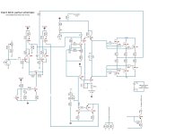
attached is the updated schematic with fixes.
Core changes:
1) Q51 emitter and collector were swapped in the original schematic
2) R107 connected to Q39 and Q40 moved to appropriate location
All pre-driver transistors attached to power supply positive and negative voltage rail via 10Ohm resistors in the power supply section. R361 and R381. I didn't add R381 but fixed R361 connection (originally R155 connected to Q37 and Q40).
Attachments

For the collector of Q53, is the difference really -40v to -4.6v?
Are you sure that R146 survived?
Does the bias make a difference?
Are you sure that R146 survived?
Does the bias make a difference?
For the collector of Q53, is the difference really -40v to -4.6v?
That is what I have measured but I have only measured it once since I was using the schematic with error and thought I was covered since I have been measuring at R107. Looking at both measurements I did I see that Q51 emitter voltage is -40V in both measurements. Also the D67 zener voltage measured -38.3V and -40V (2 different times).
Are you sure that R146 survived?
R146, R111 and R109 will burn if I keep the power on long enough. In my case with short bursts all survived but likely were cooked (still measure ok).
Does the bias make a difference?
I haven't tried changing the bias, but I have checked the resistance and they were similar to channel 4 (channel 1 and 2 from memory were closer to each other). I can try changing the bias today.
I have loaded Q51 transistor and played with 20k pot (took measurements and compared to other channels). Measured at 2 spots. The values across all channels are different. Connected to battery and only saw 1.26V DC offset. What is interesting is that I can change the offset to 0, but it won't go to negative numbers unlike other channels. Perhaps I have a bad solder joint but I couldn't find it. I checked Q64, Q65, Q66, Q67, Q51, Q52, Q53 transistors and they all measure ok (diode check and ohm readings).
Q811 (Q51) now has:
Collector: -53V
Base: -1
Q53 (Q810): collector has -5.2V
This is now in line with other measurement I have done on a good channel previously.
Q811 (Q51) now has:
Collector: -53V
Base: -1
Q53 (Q810): collector has -5.2V
This is now in line with other measurement I have done on a good channel previously.
I resoldered Q51 (Q811) and it made no difference. Here is what I have noticed, when I started to play with gain I could get the output go back to -29V. Though it was strange as I could find a sweet spot when it wouldn't do it (if I turn the pot cw or ccw) it will go to -29V. When it is not tight to the rail voltage the dc offset can be changed from 0 (500 Ohm rpot fully ccw) or negative voltage -1.3 or higher. Letting amp run for a bit I have noticed the output went back to -29V.
With output tight to -29V I have measured the Q53 pins:
Collector: -40V
Base: -40V
Emitter: -40V
The transistor is not shorted.
With output tight to -29V I have measured the Q53 pins:
Collector: -40V
Base: -40V
Emitter: -40V
The transistor is not shorted.
Last edited:
I found today R145 (100 Ohm) that was blown as well. This happened likely when I was adjusting the bias and/or probing around.
I have swapped Q811 (Q39 equivalent) and the amp had 0.136mV of DC offset on the output. I was able to adjust it in positive and negative direction. Set it to 0V offset but 40 seconds later or so the output went up to -29V. So it was stable for very short period of time.
Correction: replaced Q811 (not swapped). Also replaced Q814 and Q813. Now the offset only stays negative in -7.2 to -4V. The green overcurrent LED is lighting up... This wasn't happening before.
Have you tried heating and chiling (freezing) various areas to see if any were causing the same problems that you seem to keep encountering?
The overcurrent circuit is triggered by Q36 on the diagram. Confirm that its (equivalent) is not defective.
The overcurrent circuit is triggered by Q36 on the diagram. Confirm that its (equivalent) is not defective.
Confirmed Q36 is looking good. Replaced Q63 once again. I had some traces damaged when I was replacing it earlier and since I have been wiggling it back and force many times those pins experienced some fatigue. Haven't tried powering on the amp yet but doubt there will be a difference. The BF432 transistors I am using are made by Philips. I do see a difference when I ohm out some transistors though (could be due to different parts being used):
Q63 c+ e- 3.369 MOhm, e+ c- 3.535 MOhm; c+ b- 3.556MOhm, c- b+ 3.359MOhm
Q807 c+ e- 5.46 MOhm, e+ c- 5.74 MOhm; c+ b- 5.83 MOhm, c- b+ 5.45 MOhm
Q52 c+ e- 3.366 MOhm, e+ c- 3.526 MOhm; c+ b- 3.38 MOhm, c- b+ 3.52MOhm
Q819 c+ e- 5.49 MOhm, e+ c- 5.72 MOhm; c+ b- 5.49 MOhm, c- b+ 3.759 MOhm
Not sure if transistor gain or matching is important in this circuitry.
I would be happy to try compressed air or the heat gun but unfortunately components burn out too fast when I keep the amp on for a few seconds.
In the future, use vertical columns with one value per row, like the following. My brain takes many times longer to understand long lines of numbers.
Q63:
c+ e- 3.369 MOhm
e+ c- 3.535 MOhm
c+ b- 3.556MOhm
c- b+ 3.359MOhm
Diode check is also important. Are these out of the circuit readings?
If there is a question as to the suitability of the parts, install the replacement parts you're using in a working channel to see if that channel continues to work with the replacement parts.
Here are the latest updates of my journey.
1. On Q829 (Q38) and Q814(Q40) transistors I was measuring different resistance from known good channel after the last power on.
Q38 between Collector and Base (regardless of polarity was measuring 280KOhm and going up.
Q40 between emitter and collector 270kOhm and rising up regardless of polarity.
The output transistors were not shot, but I was measuring in 300k+ resistance across 2 pins on all output transistors.
Removed Q40 and replaced it with the original BG422 transistor, now resistance is on pair with the good channel. What's interesting is that the Q40 transistor I have removed doesn't appear to have a problem with basic diode/Ohm reading check.
2. Connected to 12V and the issue is still the same. The offset is really high likely going to get to -29V but didn't wait long enough to see what's going on. The overcurrent protection was kicking in and adjusting the offset wouldn't cure it.
3. Removed Q811 (Q51) and reconnected back, no more overcurrent protection being activated the offset can only be adjusted between 0V and + some volts. When I turned the 500k pot clockwise it was measuring 0V and stable (I let it run for a few minutes). I think I am back to my original problem but I don't recall seeing the overcurrent protection being triggered in the past.
Here is how the original and new parts compare.
Out of the circuit measurements:
BF422
Original sample 1:
b+ e- 6.47 MOhm (0.663V)
b+ c- 3.579 MOhm (0.652V)
Original sample 2:
b+ e- 6.53 MOhm
b+ c- 5.47 MOhm
New sample:
b+ e- 6.3 MOhm (0.66V)
b+ c- 5.62 MOhm (0.653V)
BF423:
Original sample 1:
c+ b- 3.42 MOhm (0.634V)
e+ b0 6.31 MOhm (0.655V)
Original sample 2:
c+ b- 5.553 MOhm (0.634V)
e+ b0 6.33 MOhm (0.654V)
New sample:
c+ b- 5.564 MOhm (0.653V could be 0.633V, cannot decipher my writing)
e+ b0 7.22 MOhm (0.684V)
I am using fluke 115 to take measurements. If I use my little portable RadioShack meter it doesn't register anything (open circuit in all cases).
In circuit measurements:
BF423
Q63:
b+ c- 3.568 MOhm
b+ e- 1.1 kOhm
c+ e- 3.382 MOhm
c+ b- 3.384 MOhm
e+ c- 3.566 MOhm
Q807:
b+ c- 5.62 MOhm
b+ e- 1.1 kOhm
c+ e- 3.605 MOhm
c+ b- 5.41 MOhm
e+ c- 5.73 MOhm
BF422
Q52:
b+ c- 3.54 MOhm
b+ e- 10 kOhm
c+ e- 3.39 MOhm
c+ b- 3.395 MOhm
e+ c- 3.546 MOhm
Q819:
b+ c- 3.752 MOhm
b+ e- 10 kOhm
c+ e- 5.43 MOhm (but if I wiggle probes up and down sometimes it will read 3.363 MOhm)
c+ b- 5.44 MOhm (but if I wiggle probes up and down sometimes it will read 3.644 MOhm)
e+ c- 5.73 MOhm (but if I wiggle the probes up and down sometimes it will read 3.761 MOhm)
With Q811 (Q51) loaded:
3B
Q52:
b+ e- 5.58 MOhm
c+ e- 3.539 MOhm
c+ b- 0.66 MOhm (sometimes 10k and rising up)
e+ b- 5.78 MOhm
e+ c- 3.545 MOhm
b+ c- 0.706 MOhm
Q811:
b+ e- 6.12 MOhm
c+ e- 5.71 MOhm
c+ b- 0.628 MOhm (sometimes 14k and rising up)
e+ b- 6.12 MOhm
e+ c- 5.71 MOhm (slowly going down)
b+ c- 0.747 MOhm
Did you try the replacement parts, one at a time, to confirm that the replacements are suitable for the amp?
- Home
- General Interest
- Car Audio
- Xtant X604 burning resistors