I recently tried to repair my blown x1001 but ran into a problem. Upon removal of the old capacitors I forgot where a little wire went. It was from fix that was done earlier. Basically I would like to see a picture of the solder side of the circuit board to see what was on the originally before it got fixed.
The wire was linking the capacitors together just don't know if it was on the positive or negative side.
The wire was linking the capacitors together just don't know if it was on the positive or negative side.
Attachments
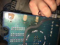
It appears that the power/ground terminal nearest the capacitors is directly connected to the capacitor terminal that's closest to the power/ground terminals. That would mean that the other cap terminals would connect to the power/ground terminal farthest from the capacitors. This is assuming that the capacitors are the primary filter capacitors for the amp.
Yeah i'm kinda of a novice but I get what your saying I think i should just send it some where. Hopefully it can still be fixed. Would you know a good place to send it.
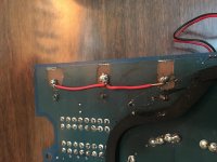
I think this is what you meant but I'm not sure. Also is the burn mark on the board mean i'm screwed and this is just a waste up time.
I replaced these but I think I didn't do a good enough job. Tell me what you think please.
I replaced these but I think I didn't do a good enough job. Tell me what you think please.
Attachments


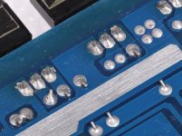
It appears that the soldering iron you're using is not applying enough heat to the connections for the solder to flow properly.
The 3 connections that you have joined with the wire need to be connected to the far power/ground terminal. Connecting with a small wire like that won't work very well, even though it may allow the amp to function. It would be better if the caps had a connection to the copper trace on the top of the board. If the vias aren't damaged, they may be connected to the top copper already.
The connections on the FETs are questionable. After soldering, the connections should be relatively uniform, similar to the ones on the FETs in the attached photo.
Attachments
Yeah you keep saying i need to connect to the far power/ground terminal but i have no idea what ya mean
- Status
- Not open for further replies.
- Home
- General Interest
- Car Audio
- xtant x1001 Repair