hey everyone,
I've been playing around with Xsim and Xmachina which are both great tools but i'm a little lost.
I use xmachina to give me a 3 way solution which it does and i then draw that out into xsim as i like the way xsim lays things out.
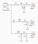
the issue i have is that whatever solution I draw out, the minute i put around 400-500w though the amp in xsim, most of my resisters are dissipating more than 100-200 watts...is this normal? I've attached my schematic.
PS..i've had to add a few resisters in parallel just to try and lower the dissipation which helps a little.
thanks for any insights!
Sal
I've been playing around with Xsim and Xmachina which are both great tools but i'm a little lost.
I use xmachina to give me a 3 way solution which it does and i then draw that out into xsim as i like the way xsim lays things out.
the issue i have is that whatever solution I draw out, the minute i put around 400-500w though the amp in xsim, most of my resisters are dissipating more than 100-200 watts...is this normal? I've attached my schematic.
PS..i've had to add a few resisters in parallel just to try and lower the dissipation which helps a little.
thanks for any insights!
Sal
Attachments
Machine has offered some irrational circuit what you have selected. If purpose of that program is to help absolute beginners who does not understand electronics a bit, program must create very rational circuits only. Not even a single useless component which is mostly dissipating power.
Another very good option is to study and use basic crossover circuits, optimize manually or with iterating optimizer. Then you can trust yourself and use any other program.
XSim calculates power consumption with continuous flat response signal. Actual music signal is usually very different. "Some other program could have" possibility to estimate also signal spectrum and crest factor 🙂
thanks for the response.
i assumed that xsim would be quoting me with a continuous tone bit even so, what's the best way of calculating which resistor power i will need without the crossover failing?
I've managed to get my circuit down to respectable resistor power levels of 100w but another problem is that 100w and above resistors are huge and i'd need a huge board to accommodate all the crossover components.
I know resistors can withstand pretty high spikes or powers without degrading so not sure if i can get away with installing 50w resistors or less?
any advice is appreciated.
Sal
Can you find out the efficiency of the resulting speaker?
Is it correct that your bass speaker is more efficient than the mid and tweet?
//
Is it correct that your bass speaker is more efficient than the mid and tweet?
//
One other thing to consider is what the real life wattage that you will be putting through a circuit will be. Unless you are in an outdoor venue or a large auditorium, I think it unlikely that each speaker will be seeing 400-500 Watts. I would be surprised if your speakers saw a tenth of that in typical listening environments. Having amplifiers with extra headroom helps to protect against distortion damage to the speakers.
One other thing to consider is what the real life wattage that you will be putting through a circuit will be. Unless you are in an outdoor venue or a large auditorium, I think it unlikely that each speaker will be seeing 400-500 Watts. I would be surprised if your speakers saw a tenth of that in typical listening environments. Having amplifiers with extra headroom helps to protect against distortion damage to the speakers.
Clarification: I am speaking about wattage ref. to the voltage.
Well the speakers will be used in live environments such as live bands and DJing so music will constantly be loud but obviously not constantly pumping 400-500 watts. I have an xti 4002 which gives me around 600watts per ch at 8ohms and is usually constantly just under clipping during performances so just wanna be sure I'm building the crossovers to my needs.
I never thought of this, but I'm currently using off the shelf B&C Crossovers that I had lying around as a temp solution and they've been fine for over 6 months and they only have 20w resistors! I think I've answered my own question...
I never thought of this, but I'm currently using off the shelf B&C Crossovers that I had lying around as a temp solution and they've been fine for over 6 months and they only have 20w resistors! I think I've answered my own question...
Woofer should not need resistors for other than BSC and impedance correction trick in some rare cases. 10W resistors are normal maximum. 20W might be needed for BSC or if mid driver is 4 ohms and several dBs more sensitive (USPL) than the others and Q-value of 2nd order LP/HP filters is on high side.
Why? Music spectrum is close to pink noise ie -3 dB/oct >2kHz, and relation of peak and RMS is probably 8...20 dB. So, power dissipating in drivers and other resistances could be 1/10 of amplifier's maximum output power to nominal impedance. I've never burned 20W resistor with for example ICEpower 1000 W/4ohm, volume knob close to max with USPL=90 dB/2.83V/m speakers. Of course it's possible if crossover is not designed with common sense.
Active system is worth to consider if >20W resistors are really needed and not just a bad dream / misleading simulation. For example with PA systems.
...and you can always double check power dissipations with VituixCAD which has spectrum and crest factor (peak/RMS) parameters in Power dissipation window. XO design is probably bad if 20W is exceeded with pink >2kHz and crest factor ~10 dB.
Thanks kimmosto!
The crossover was designed by xmachina over 12hrs so I can only assume the design makes sense otherwise it's a worthless piece of software. I think I'm just being extremely causious about what I'm building but you've shed some good light for me. I've got vituixcad so will defo try it out.
Thanks again!
the issue i have is that whatever solution I draw out, the minute i put around 400-500w though the amp in xsim, most of my resisters are dissipating more than 100-200 watts...is this normal? I've attached my schematic.
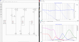
The schematic can be easily transformed into a more readable form, it is enough to swap impedances in some branches.
Now, if I'm guessing correctly, your target dBspl is set much lower than the dBspl of the speakers applied, hence the need for signal attenuation.
To fix it and get rid of resistors from the woofer circuit try to click your target spl again in an easy way - just follow spl of your woofer almost up to the first crosspoint.
In a high power system as yours I'd consider doing the same for the midrange driver, at least on the LF side. (If it is impossible, i.e. the system requires intensive corrections of the low frequency range then, based on my very modest experience, maybe an active solution would be better.)
Check out also your impedance target, for example setting it as 8R with 4R drivers may also cause adding resistors to the circuit.
Attachments
Thats exactly the issue, the mid driver, albeit no slouch, can't keep up with neither the bass nor the tweeter hence the atteuation....although I can try and alter the target spl to get the best solution, didn't really think of doing that for some reason.
I'm also very close to choosing an active solution and not as expensive as I thought!
All this has been so helpful, thanks for all comments!
I'm also very close to choosing an active solution and not as expensive as I thought!
All this has been so helpful, thanks for all comments!
Get rid of the mid resistors and the bass resistors. The latter wrecks havoc with the damping ffactor. If the bass it to much for the midrange use a baffel step filter to lower the level of upper bass.
Bass 98db
Mid 99db
High 113db
You want NO series resistors on the Bass and Mid. Resistors do not make sound, just throw-away precious power.
Beware any solution with series resistors as large as the driver impedances.
While I'd say 98 and 99 dB are "same", an "exact" solution might put a part-Ohm series in the Mid. I would NOT do this. Power is too precious to waste. The 1dB difference may be an illusion of the different dispersion patterns. And a 1dB correction is best tweaked in a low-level EQ tool.
The High appears to need 14dB attenuation, which will use a large series resistor. Unless you are trying to beam the music across the lake, I am sure this is wrong. A High horn can be beamy in a modest size. But in a room, even in a park, the *total* acoustic output must be balanced. I would expect to use 6dB-12dB attenuation on the High horn.
No resistors for woofer, but mid is not that simple. Added series resistance could improve linearity and reduce IM distortion especially with non-conductive voice coil former. Advantage of current drive.
Thanks for the replies. I've decided to go active this time round and then maybe in future, when I have some spare cash to try the crossover, I'll build one but I'm trying to build my very 1st crossover and I've decided on a 3 way, a bit ambitious. I've managed to take away resistors on the sub and the midrange but obviously attenuation is needed on the tweeter.
- Status
- Not open for further replies.
- Home
- Design & Build
- Software Tools
- xsim calculations