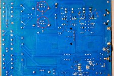
First put all 2 opamps out. Measure dc from rca gnd to all 8 dip socket voltages... So pin 1 xx volt. Then we are going on. And please measure dc on output of dac voltages before first and after first resistors... This blue 4 pcs that shows 10..11v dc.
Ok, here: 8-dip sockets:
1- 00.1V
2 - 06.3V
3 - 03.0V
4 - 06.9V
5 - 00.0V
6. - 06.3V
7 - 31.0V
8 - 00.0V
The resistor:
(10kohm) 06.5V (11kohm) 06.5V before the resistors
(10kohm) 03.1V (11kohm) 06.4V after the resistors
1- 00.1V
2 - 06.3V
3 - 03.0V
4 - 06.9V
5 - 00.0V
6. - 06.3V
7 - 31.0V
8 - 00.0V
The resistor:
(10kohm) 06.5V (11kohm) 06.5V before the resistors
(10kohm) 03.1V (11kohm) 06.4V after the resistors
Last edited:
Pin 4 and 7 are totally wrong...can you please tell me why are 6 holes in regulator place...
make picture near regulator pins top side ...are they lm317..337?
underneath What is DC on both big capacitors?
make picture near regulator pins top side ...are they lm317..337?
underneath What is DC on both big capacitors?
Attachments
Last edited:
The regulators are LM294 Shared album - Mykhailo M - Google Photos
and MFC26 Shared album - Mykhailo M - Google Photos
The CD reading on BIG Caps (3 caps) shows zero 00.0 reading - I guess it shouldn`t be
and MFC26 Shared album - Mykhailo M - Google Photos
The CD reading on BIG Caps (3 caps) shows zero 00.0 reading - I guess it shouldn`t be
Last edited:
No no not lying ones... That hiden under the heatsink. I see Mje transistor Cant be zero Dc because on opamp pin you have 31 and 6.9V. Press tips harder into solder and measure dc.
Last edited:
Near the heartsick 31.7V
The Big ones caps 4 of them. (still don`t know how to add the photo here as it asks for my URL address)
Here is the link: Mykhailo M - Google Photos
The Big ones caps 4 of them. (still don`t know how to add the photo here as it asks for my URL address)
Here is the link: Mykhailo M - Google Photos
An externally hosted image should be here but it was not working when we last tested it.
Last edited:
If you have 54v and 30v your input transformer is not connected in 230 but in 115v. First solve this then we will check if anything is burned. So central tapes of input are tight together and not connected to no. Point other 2 one on phase one on neutral of power plug
And buy at least one ne5534 or tlo71 for 0.5€ to disclose opamp failure, because earlier-original JRC is dead if he became 31v on both rails. Can be that damaged opamp has also damaged regulator.
Hi, On the transformer the marking for Red in 230V and this is the one I connected to mains + Black to neutral. I this op-amps OK: NE5534P Low Noise Op Amp NE5534 5534 (2 Pack) | eBay
Should I buy new JRC and what is the JRC?
Should I buy new JRC and what is the JRC?
What have you done with green?
Maybe colour code is not right ... disconnect primary and measure resistance from red to green and from black to green... sum from red to black must be equal as from black to green and green to red. Maybe they have mixed and you have 115v connection.
Jrc is producer like Texas instruments and Phillips...they all produce NE5534.
You get this opamp in all local electronic shop for almost nothing no need to wait for ebay delivery.
ne5534 - Search Results | Farnell UK
First you must solve right voltages on all pins.
Hi,
The green is left unconnected and isolated. The resistance (Green 115v -- Red 230v)(on multimeter set to 200Ohm)
a) red to green 87.2
b) black to green 45.4
I have another transformer I have (115v Orange --230v Red) the readings:
a). red to orange 83.7
b).black to orange 43.0
The green is left unconnected and isolated. The resistance (Green 115v -- Red 230v)(on multimeter set to 200Ohm)
a) red to green 87.2
b) black to green 45.4
I have another transformer I have (115v Orange --230v Red) the readings:
a). red to orange 83.7
b).black to orange 43.0
Last edited:
In that case red and green are right wires and black is middle insulated wire.
China i got often problems with boards ...
1.disconnect secondaries from dac board except for audio part (yellow and brown)
2.connect green to neutral red to phase ... black isolated
3.measure DC on 2 big capacitors where you measure 50V DC
China i got often problems with boards ...
1.disconnect secondaries from dac board except for audio part (yellow and brown)
2.connect green to neutral red to phase ... black isolated
3.measure DC on 2 big capacitors where you measure 50V DC
Here is the picture of connection (Black is ground and disconnected / isolated) Shared album - Mykhailo M - Google Photos
Should I turn in on to measure?
Should I turn in on to measure?
First measure resistance from black to red if it is 45 then Yes turn on if you hear buzz in transformer then turn off...if no then measure dc on big caps. If it is 25V DC then measure dc in DIL8 pins 4 an 7.
Write (-) if it is negative dc.
Write (-) if it is negative dc.
121 is sum and your earlier connection is ok. Hmm than unplug and measure resistance between 2 yellow and 2 brown. resistance from yellow to brown must be 0.
help tips Wioth U-208 Problem
Hi Ya All...
I Ralize this is quite an old thread nowadays....
I thought if i Could help Even One Person, Then ALL GooD 🙂
But have You asured that the powersuply setup matches the needs of
Witch i thought Strangley Stringent Listed in one of the PDF Files From The Xmos Site,
For the measly qf48 208 chip,, Wich If i remember Corectly from one of the countless PDF Files i Read & Plowed trough a Few Years back in my Resaearch back in those days, From The xmos Site....
The Point Being wich was one that stumped me a little bit,,
But if the PDF File Is Corect the U-208 Chip expects Full Power uP Within in 2o MilliSeconds,
i Canot remember if this was on all power pins (Probably Not)
It Maybe Clock/Timing related, Wich means u dont only need a good powersuply But you need a Fast One To.......
Bests Of regards To All Ya Hi_Fi Soul Lovin People.............

- Home
- Source & Line
- Digital Line Level
- !!! Xmos Problem !!! Dual AK4495S AK4495SEQ AK4118 DAC decoder XMOS USB w/LME49990