Recently built the John Broskie "Unbalancer" PCB:
The Unbalancer
I'm using a DAC which has two AD1865 chips, and true balanced output - the i/v stage is passive via a resistor so the dac output is only about 200mV. Hence I thought it would be great to kill two birds with one stone and get good voltage gain and CMRR using Broskie's linestage design.
Here comes the hard part - controlling the volume with remote control.
I bought a "LITE MV04" kit:
4 Way Motorized Remote Control KIT set MV04
It has RCA and XLR inputs, and also does either RCA or an XLR output.
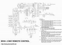
HOWEVER, upon receiving the kit & manual (see attached) pdf, turns out the XLR output (which I intended to run to the Broskie PCB) is not true balanced - as you can see in the schematic the circuit accepts a true balance input - 3 wire signal but the output (BN7) is only 2 wire signal (L & R) so it is not a true balanced output.
What would the best plan be to maintain good CMRR in this situation?
The Unbalancer
I'm using a DAC which has two AD1865 chips, and true balanced output - the i/v stage is passive via a resistor so the dac output is only about 200mV. Hence I thought it would be great to kill two birds with one stone and get good voltage gain and CMRR using Broskie's linestage design.
Here comes the hard part - controlling the volume with remote control.
I bought a "LITE MV04" kit:
4 Way Motorized Remote Control KIT set MV04
It has RCA and XLR inputs, and also does either RCA or an XLR output.
HOWEVER, upon receiving the kit & manual (see attached) pdf, turns out the XLR output (which I intended to run to the Broskie PCB) is not true balanced - as you can see in the schematic the circuit accepts a true balance input - 3 wire signal but the output (BN7) is only 2 wire signal (L & R) so it is not a true balanced output.
What would the best plan be to maintain good CMRR in this situation?
Attachments
Common mode rejection occurs in the *receiving* device. It can be degenerated by impedance imbalance but is independent of signal balance.
All good fortune,
Chris
All good fortune,
Chris
Common mode rejection occurs in the *receiving* device. It can be degenerated by impedance imbalance but is independent of signal balance.
Not sure I follow - isn't the receiving device in this case the MV04?
In any case, would you recommend:
(1) DAC with XLR output -> Lite MV04 (true XLR input, RCA output) -> Broskie Unbalancer PCB
OR
(2) DAC with XLR output -> Lite MV04 (true XLR input, 'not true' XLR output) -> Broskie Unbalancer PCB
I didn't look at the schematic but "not XLR" does not mean "not balanced".
Balanced just means that there are two signal wires for one channel, with the signal on one wire being an inverted copy of the signal on the other. When they are "recombined" through a differential amplifier, anything that was the same on both wires (i.e. "common mode") gets cancelled out.
Balanced just means that there are two signal wires for one channel, with the signal on one wire being an inverted copy of the signal on the other. When they are "recombined" through a differential amplifier, anything that was the same on both wires (i.e. "common mode") gets cancelled out.
OK - how do we determine whether the "false" xlr output of this volume controller is, in fact, balanced or not?
BN7 can provide a ballanced output.......pos and neg for left and the same for right plus a common ground .......provided the correct connections are made at XP2 and XP3.......seee the schematic notes .
Last edited:
Balanced refers to the impedances not the signals.
A balanced connection works just as well with
a.) two in phase signals of different amplitude
b.) a single amplitude signal and a zero amplitude signal
c.) a pair of opposite phase signals of the same amplitude
d.) a pair of opposite phase signals of different amplitude
The common factor of all of those different signal arrangements is that the impedances of the two signal connections are close to identical. The closer to identical (including resistance and inductance and capacitance) the better that the balanced impedance connection performs it's job, i.e. to reject interference.
Balanced refers to the impedances not the signals.
A balanced connection works just as well with
a.) two in phase signals of different amplitude
b.) a single amplitude signal and a zero amplitude signal
c.) a pair of opposite phase signals of the same amplitude
d.) a pair of opposite phase signals of different amplitude
The common factor of all of those different signal arrangements is that the impedances of the two signal connections are close to identical. The closer to identical (including resistance and inductance and capacitance) the better that the balanced impedance connection performs it's job, i.e. to reject interference.
Really? I thought that for the standard balanced audio outputs and interconnects it had to be c. Otherwise, standard "balanced inputs" audio equipment wouldn't handle it correctly.
If the source impedances are the same, what happens when you inject a common mode current? Even if one side has a signal and the other side doesn't? You get a common mode voltage, which will then be rejected. Now, suppose the source impedances were different and the signal voltages were exactly equal in magnitude and opposite in polarity. Then the common mode current will be partially converted to a differential voltage. All the balanced input cares about is the differential voltage, not how that differential voltage was obtained.
There's lots of confusion on this topic, and I think that most comes from the use of the word "balanced". It's the kind of thing that started with a fairly well understood meaning, and grew, and grew, until it means almost nothing specific now.
In classic pro sound environments there's floating and non-floating "balanced" and in prosumer environments there's impedance "balanced", etc. But the magic doesn't happen at the sending end of things, it happens at the receiving end, and the important part is that the receiving end be differential.
All inputs, even single-ended ones, are differential to some extent, but those made to reject common mode signal/noise are called "balanced". A poor choice of terms but we're stuck with it.
For a differential input to work properly it's only necessary for source impedances to be equal, and signal imbalances don't matter, as several good folks have said better.
All good fortune,
Chris
In short - it doesn't particularly matter how the signal is delivered to the Broskie Unbalancer stage, it's just that the impedances are unchanged from the DAC to the Volume Controller, and through the preamp stage?
No.But the magic doesn't happen at the sending end of things, it happens at the receiving end, and the important part is that the receiving end be differential.
Both the receiving and transmitting ends must be balanced. Read Jung & Whitlock.
Both the receiving and transmitting ends must be balanced.
If by "balanced" you mean that impedances must be equal, and if we're discussing common mode rejection, then yes, both ends must be "balanced". If we're discussing some other quality, for example inter-channel coupling between unshielded pairs, etc., then other rules will apply.
For regular home audio use, with separate shielded wires for each channel's signal, impedance balancing is all that's needed, because common mode rejection is all that's needed.
Thanks,
Chris
ps: And usually not even that. Ground loops should be fixed another way.
For those that are a bit rusty on balanced analog audio interconnects the Rod Elliott edited, Bill Whitlock paper might be a good review.
Design of High-Performance Balanced Audio Interfaces
Bill Whitlock - Jensen Transformers, Inc.
Balanced Interfaces
Design of High-Performance Balanced Audio Interfaces
Bill Whitlock - Jensen Transformers, Inc.
Balanced Interfaces
For those that are a bit rusty on balanced analog audio interconnects the Rod Elliott edited, Bill Whitlock paper might be a good review.
Design of High-Performance Balanced Audio Interfaces
Bill Whitlock - Jensen Transformers, Inc.
Balanced Interfaces
It's a good article, and it includes an excellent cartoon...
Attachments

lordearl,
I apologize profusely for confidently posting incorrect information in my reply to you.
Everyone else,
Thank you for taking up my slack (and for teaching me something). From now on, I'll try to at least not sound confident about things that I haven't personally played around with, or verified.
Regards,
Tom
It has been a great read - an informative, but I'm not sure I have a clear solution to my original problem 😕
Sorry, we've ducked the question. I'm not familiar with the Broskie device, but if you say it has a good common mode rejection and if you want the common mode rejection for the purpose of nulling distortions common to both polarities of the D/A convertors, then you definitely want it to follow the D/A convertor immediately. Inevitable mistracking of the volume control pots would disturb your common mode rejection significantly.
If these are not your goals, you'll need to spell 'em out a little more.
All good fortune,
Chris
If these are not your goals, you'll need to spell 'em out a little more.
All good fortune,
Chris
Really? I thought that for the standard balanced audio outputs and interconnects it had to be c. Otherwise, standard "balanced inputs" audio equipment wouldn't handle it correctly.
Just an FYI, the commercial Sony BetaCam series decks (BVW-70/BVW-75) had a design error in it and every one of them (MANY thousands) has an imbalance of the XLR outputs because they used all the same value resistors in their output amplifiers but one phase runs non-inverting and the other as an inverter. They forgot the non-inverter gain is 1+r1/r2. I only found it one day about 15 years ago when looking at the individual phases and went, WHAT??
Another FYI is virtually all broadcast gear runs unbalanced internally and converts back to balanced at the output. Running a balanced routing switcher would double the number of crosspoints and in a 144x144 switcher this can be substantial aka prohibitive. The 'improvement' is unmeasurable.
Bottom line is with good unbalanced amplifiers there really is very little to be gained by running balanced. BUT I AM an advocate of running balanced input sections even when sourced with unbalanced signals as you can 'subtract out' any ground loop noise between units, though this is not a common problem. The cost penalty for differential inputs is a few resistors per input.
G²
- Status
- Not open for further replies.
- Home
- Source & Line
- Analog Line Level
- XLR, RCA and CMRR - a few questions