Hi,
I've just assembled my XBosoz (Karis pcbs, Coloumbs parts), but unfortunately, I have some problems...
When I tested the PSU without any load, both channels work very nice and delivers the correct voltage. Then I connected the amp pcb...
No smoke
I measured the voltage at the PSU connection and get very low values, - strange. At the same time it starts to smoke from (I think) the smaller negative rail 220 uF cap so quickly turn the power off.
This happens with one of the PSUs, the other I get no chance to measure and I dont see any smoke.
I disconnect the Xbosoz PSU and measure the voltage that the PSU cards delivers, the smoking one delivers +80,-20 and the other +64, -13.5
I have some questions, I hope you excuse my ignorance! This is my first Pass amp and it is difficult for an biochemist to follow the electrons of this construction...
To the questions...
I suspect that I have some problems with the Xbozos cards that cause the malfunction of the PSU - any suggestions is appreciated! Is it likely that the Xbozos has been damaged as well?
Then I have the problem with the smoking card, even an biochemist understand that something in the voltage regulation is broken, but where should I start? I dont want to connect the PSU to the transformator to measure it, and how can I control if any of the caps are broken? And why did it start the smoke from a cap rated at 100 V when the voltage at the negative rail is 20 V?
The other strange thing is the non-smoking PSU that delivers +64, -13.5, what can be the problem with this one? My own interpretation is that the IRFs are blown?
I would really appreciate some assistance!
Thanks all for your responses! It felt very desperate yesterday evening but with your support it feels much more optimistic and it should be possible to find what is wrong!
")
The mods I've done on the PSU cards is to solder D1-D4 in the same direction as D5-D8. I've also soldered D9 and D10 according to the modification.
The PSUs delivered the right voltage until I attached the Bosoz pcbs. I suppose this means that the reason for the error is on these cards even though the PSU broke as well. I suspect a short circut, that may explain the smoke from the PSU caps?
Thanks Anthony. I'm a litte bit worried about the 220 uF caps on the PSU. I suppose the smoke indicates that something may be broken. I'll try to measure them tomorrow. If necessary, I found an ELNA RJH longlife, or possibly a Sanyo MV-AX replacement. Do you think any of these can substitute the Nichicons.
Anyway, I have to buy a new multimeter before I can check the Nichicons. I had a really bad evening yesterday. First the Bosoz broke, two hours later, while trying to localize the problem my multimeter broke as well .
.
Do I need to tell you that its orbiting the earth on a very high altitude right now?
I will order some 9.1 and 4.5 zeners from a local source and I suppose the IRF9610 and IRF610 on the PSUs is broken as well. Is a rating of 0.5 W sufficient for the zeners?
Do you think something else may be broken?
My real worries are the Bosoz cards. Suppose I feed them with 80, -20 V, what will be broken? All the IRFs? I didnt se any smoke from any of these, so maybe, hopefully they are not do severely damaged.
I really appreciate your help!
If you search the XBOSOZ thread by Kari you'll find that silkscreen on some diodes are reversed and I think on the copper circuit design too. Subsequently a walkaround solution for this mistake was made.
The mods I've done on the PSU cards is to solder D1-D4 in the same direction as D5-D8. I've also soldered D9 and D10 according to the modification.
The PSUs delivered the right voltage until I attached the Bosoz pcbs. I suppose this means that the reason for the error is on these cards even though the PSU broke as well. I suspect a short circut, that may explain the smoke from the PSU caps?
Trango if you need replacement parts let me know.
Thanks Anthony. I'm a litte bit worried about the 220 uF caps on the PSU. I suppose the smoke indicates that something may be broken. I'll try to measure them tomorrow. If necessary, I found an ELNA RJH longlife, or possibly a Sanyo MV-AX replacement. Do you think any of these can substitute the Nichicons.
Anyway, I have to buy a new multimeter before I can check the Nichicons. I had a really bad evening yesterday. First the Bosoz broke, two hours later, while trying to localize the problem my multimeter broke as well
. Do I need to tell you that its orbiting the earth on a very high altitude right now?
I will order some 9.1 and 4.5 zeners from a local source and I suppose the IRF9610 and IRF610 on the PSUs is broken as well. Is a rating of 0.5 W sufficient for the zeners?
Do you think something else may be broken?
My real worries are the Bosoz cards. Suppose I feed them with 80, -20 V, what will be broken? All the IRFs? I didnt se any smoke from any of these, so maybe, hopefully they are not do severely damaged.
I really appreciate your help!
I should have spares on the Zeners and IRF Fets for a few bucks.
The Elna cap should be fine for the 220uf, though I have spares as well.
As far as the preamp boards the higher voltage should not have really damaged the parts, the FETS are good to 150VDC I think. Just check the IRF website for the specs.
Anthony
The Elna cap should be fine for the 220uf, though I have spares as well.
As far as the preamp boards the higher voltage should not have really damaged the parts, the FETS are good to 150VDC I think. Just check the IRF website for the specs.
Anthony
In my opinion, PSU unit is simpler than the amp unit.
First, I would be sure of PSU, then would check others.
0.5W zener is big enough. If the zener is of 9.1V, it could have max current of about 0.5/9.1*1000=55mA. As far as I understand, we in general arrange about 10mA or less current. I have always used 0.5W size.
I have some experience of smoking and explosion with the reversed connection of cap polarities. I however have no experience of smoking caps when all polarities and voltage ratings are in right place. In my opinion, the smoking could have happened actually from another element placed near the cap. I have also often confused by optical effects.
For your info. When I have a problem in the amp side, I always compare the fabricated board with the circuit diagram. I select any one soldering joint, and check whether all components connected to this joint are correctly placed, sized and directed. Then go to the next joint, the next, . . . until I finish all joints.
Good luck,
phoneisbusy said:Hi Coulomb,
Could you please email me? I haven't been able to get in touch with you via email.
Dave
Sorry Dave, have some email issues at home, I will PM my work address to you.
Anthony
Thanks for all replys!
I've bought a new fancy multimeter so now I'm back!
OK, I start with the smoking PSU!
You are right jh6you. I attached the PSU to the trafo (without the boz card) and checked which component that smoked. It is R3 (1.5 kOhm). I've measured the resistance to 1.494 so I guess the resistor is not damaged even though the plastic of the resistor is somewhat burnt.
I've tried to find a circut diagram of the PSU without any success so I don't really understand what would cause the high current through R3?
Thanks Anthony. You've got PM!
/Fredrik
I've bought a new fancy multimeter so now I'm back!
In my opinion, PSU unit is simpler than the amp unit.
OK, I start with the smoking PSU!
I have some experience of smoking and explosion with the reversed connection of cap polarities. I however have no experience of smoking caps when all polarities and voltage ratings are in right place. In my opinion, the smoking could have happened actually from another element placed near the cap. I have also often confused by optical effects.
You are right jh6you. I attached the PSU to the trafo (without the boz card) and checked which component that smoked. It is R3 (1.5 kOhm). I've measured the resistance to 1.494 so I guess the resistor is not damaged even though the plastic of the resistor is somewhat burnt.
I've tried to find a circut diagram of the PSU without any success so I don't really understand what would cause the high current through R3?
I should have spares on the Zeners and IRF Fets for a few bucks
Thanks Anthony. You've got PM!
/Fredrik
I really like your picture, it even looks like me!
After a few days of cooling down I actually think I may turn this into a very good lession of electronics. I've previously built a few amplifiers and active crossovers and they have worked out just fine. But I havent learnt very much of these project. Now, I really have to check the circut and think about what has happend. Thats a good lession!
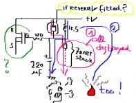
The diodes are in the right direction, at least according to this picture
http://www.briangt.com/gallery/album12/DSC00417
But it seems like something has happend to the FET. If I measure the resistance between the drain (which I suppose is the right pin of the FET) and the ground (the middle pin of the FET) i get no resistance at all. I suppose that such a short circut may allow to much current through R3.
I thought this was strange since I use a 1 A fuse at the primary side, however, when I checked the fuse I discovered that it actually is a 10 A fuse. I keep all my fuses is a box with several compartments, I guess a 10 A someway has found its way into the 1A compartment.
Anyway, my current working hypothesis is that both PSUs are soldered correctely and that they were fine until I attached a Boz card with a short circut someware. The 10 A fuse allowed to much current through the zeners and FETs and blew these.
Any opinions?
/Fredrik
After a few days of cooling down I actually think I may turn this into a very good lession of electronics. I've previously built a few amplifiers and active crossovers and they have worked out just fine. But I havent learnt very much of these project. Now, I really have to check the circut and think about what has happend. Thats a good lession!
The diodes are in the right direction, at least according to this picture
http://www.briangt.com/gallery/album12/DSC00417
But it seems like something has happend to the FET. If I measure the resistance between the drain (which I suppose is the right pin of the FET) and the ground (the middle pin of the FET) i get no resistance at all. I suppose that such a short circut may allow to much current through R3.
I thought this was strange since I use a 1 A fuse at the primary side, however, when I checked the fuse I discovered that it actually is a 10 A fuse. I keep all my fuses is a box with several compartments, I guess a 10 A someway has found its way into the 1A compartment.
Anyway, my current working hypothesis is that both PSUs are soldered correctely and that they were fine until I attached a Boz card with a short circut someware. The 10 A fuse allowed to much current through the zeners and FETs and blew these.
Any opinions?
/Fredrik
trango said:. . .
the drain (which I suppose is the right pin of the FET) and the ground (the middle pin of the FET) . . .
?? I am a bit confused . . .
Attachments
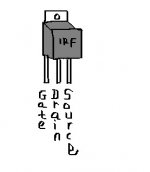
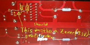
Are you sure that you inserted IRF pins correctly into PCB?
It seems that you got them in 180 deg turn, and attached a diode instead of the zener . . .
Take time and drink some cold beer . . .
In similar cases, I always drink, drink, drink, . . . and come back to the battle few days later.
Regards
JH
It seems that you got them in 180 deg turn, and attached a diode instead of the zener . . .
Take time and drink some cold beer . . .
In similar cases, I always drink, drink, drink, . . . and come back to the battle few days later.
Regards
JH
jh6you, I'm really greatful for your help!
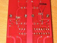
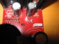
I think my ignorance cause many missunderstadings. It is a 9.1 zener between the gate and the source. And I've placed the FETs according to the silkscreen. I've attached a couple of pictures to avoid further missunderstandings! Note that R3 has been partly removed to allow measurements.
I think my ignorance cause many missunderstadings. It is a 9.1 zener between the gate and the source. And I've placed the FETs according to the silkscreen. I've attached a couple of pictures to avoid further missunderstandings! Note that R3 has been partly removed to allow measurements.
Attachments
- Status
- This old topic is closed. If you want to reopen this topic, contact a moderator using the "Report Post" button.
- Home
- Amplifiers
- Pass Labs
- Xbosoz HELP (Karis PCB)