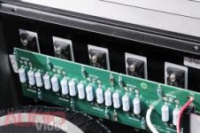
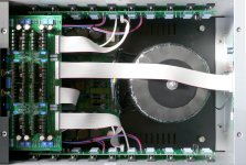
The XA.8 has a new single-ended current source. See the pictures of the XA30.5 and the XA30.8. On the picture of the XA30.8 I see a Cap and JFET or transistor.


It looks like the resistors have been replaced with a JFET current source, see image 15 of the following link:
https://www.passdiy.com/project/amplifiers/diy-op-amps
I somehow miss the clue how this works. Is there a Pass Labs article that describes the resistors vs JFET current source?


It looks like the resistors have been replaced with a JFET current source, see image 15 of the following link:
https://www.passdiy.com/project/amplifiers/diy-op-amps
I somehow miss the clue how this works. Is there a Pass Labs article that describes the resistors vs JFET current source?
Not really, but you can pretty much get the idea of how a current source
works. A power resistor is a current source of sorts, and we have used
that sort of approach in some earlier products, but we wanted to step up
the amount of single-ended bias used, so in the Xs and .8 products you
will see constant current sources instead, giving more current at higher
impedance.
We have been doing that sort of thing in one form or another since the
Aleph 0 in 1992, and you can read some about it in the article "Leaving
Class A" on the First Watt website.
😎
Besides Nelson's comment I cannot believe to get enough current with a TO92-device to make an effective CCS.
Resistors in their earlier passive CCS were at least 3W-types.
Resistors in their earlier passive CCS were at least 3W-types.
Is there anybody that has the Aleph 0 service manual and that is willing to send it to me? The links to the Aleph 0 documents on this forum don't work anymore.
Besides Nelson's comment I cannot believe to get enough current with a TO92-device to make an effective CCS.
Resistors in their earlier passive CCS were at least 3W-types.
TO92 can govern bigger critter

Last edited:
Is there anybody that has the Aleph 0 service manual and that is willing to send it to me? The links to the Aleph 0 documents on this forum don't work anymore.
shoot me at >sasica5@gmail.com<
Besides Nelson's comment I cannot believe to get enough current with a TO92-device to make an effective CCS.
Resistors in their earlier passive CCS were at least 3W-types.
100% agree with the comment of hm4nine!!! 😎
According to the article 'leaving class A' and my calculations the single ended bias is about 100mA. Should not be a problem for a to-92.
According to the article 'leaving class A' and my calculations the single ended bias is about 100mA. Should not be a problem for a to-92.
you want to review your calculations 🙂
If you assume 2x25VDC for supply, you will have 2,5W on a TO92 for 100mA.
You will have SE only a few moments....
You will have SE only a few moments....
If you assume 2x25VDC for supply, you will have 2,5W on a TO92 for 100mA.
You will have SE only a few moments....
hm4nine.....you didn't need to ruin the calculation exercise for the guy.....that is exactly why I didn't spoil it for him in the first place....ahahahahah 😱
😎
Stefanoo ... none of us is immune not to be misleaded sometimes.
I am sure that our collague MEnsing was too much fixed for SE-biasing and not into calculations.
But in our community we should help each other....for our beloved hobby.....
I am sure that our collague MEnsing was too much fixed for SE-biasing and not into calculations.
But in our community we should help each other....for our beloved hobby.....
According to the article 'leaving class A' and my calculations the single ended bias is about 100mA.
The article doesn't say, and perhaps your calculation is incorrect. The bias
is much higher than that.
😎
Is it possible that the output stage is acting like a large current source that is actively controlled by the FE? No need for extraneous circuits, with anyaniupulation of output current being controlled by the FE
The article doesn't say, and perhaps your calculation is incorrect. The bias
is much higher than that.
😎
yes besides that exactly!! I was just going to say the same thing but then I decided to save it for after we would have solved the topic why a TO92 cannot handle not even 100mA....ahahahaha!!! 😎
Last edited:
Stefanoo ... none of us is immune not to be misleaded sometimes.
I am sure that our collague MEnsing was too much fixed for SE-biasing and not into calculations.
But in our community we should help each other....for our beloved hobby.....
true hm4nine....you are right.
IMO helping him means to help him reason and try at least to understand why his conclusion was wrong.....
but definitely...hands down....you are a very nice guy!!!! 😉
Is it possible that the output stage is acting like a large current source that is actively controlled by the FE? No need for extraneous circuits, with anyaniupulation of output current being controlled by the FE
the SE output stage acts like a current source that constantly bias the output stage to a specific value to keep the behavior really similar to a SE topology kind of thing, until load requires more current, in which case it behaves as a classic push pull!
Yes. You could have a CS in the form of a resistor or an active stage in parallel with the ouput stage. Could these same effects be achieved simply by manipulating the FE/Vas stage without the need for any sort of parallel circuit in the output.
Yes. You could have a CS in the form of a resistor or an active stage in parallel with the ouput stage. Could these same effects be achieved simply by manipulating the FE/Vas stage without the need for any sort of parallel circuit in the output.
sorry, not that I can at least personally think of...but perhaps Master Nelson might have more creative solutions to your idea.
To obtain a SE behavior or in other words the typical spectral distribution of a SE design which has a distinct nice sonic signature, you will need a current source at the output stage and the idea of having a current source mixed up with a PP output stage is a brilliant idea that IMHO combines a bit of both worlds.
Now, you can achieve this with a simple power resistors (or likely multiple resistors in parallel depending on many factors), but you have to be aware of the fact that your SE biasing will vary as the output swings up and down creating an unwanted modulation effect.
Best solution is what Nelson likely adopts on his new commercial designs, i.e. actually having a series of dedicated active source devices at the output, which are sharing the same heatsink.
Better sound overall and also nicer aesthetically...or in other words more pleasing to the eyes and to the ears!
😎
Yes. You could have a CS in the form of a resistor or an active stage in parallel with the ouput stage. Could these same effects be achieved simply by manipulating the FE/Vas stage without the need for any sort of parallel circuit in the output.
let me take this back...I think you can do that...but I think you will need to AC couple at the output, also I don't think the harmonic distribution will result in a nice signal, given that your distortion contribution by the different quadrant circuit won't be much symmetric anymore.
Hope this makes sense....but again Nelson can certainly provide you with a better and more reliable answer to your question.

- Status
- Not open for further replies.
- Home
- Amplifiers
- Pass Labs
- XA.8 single-ended current sources