Hello lhquam. I did not find a circuit which is an example of Cascode Local Feedback [CLF]. So I used its descriptive words [CLF] to write a schematic which maybe or not the desired subject.
The image shows your artwork from post #94. In the top right corner is this possible CLF schematic; with focus on Q8 and Q4 below it as an example. The joint emitter of Q8 and the drain of Q4 is a summing junction where the two out of phase signals combine.
Best regards.
My first comment is to forget about the schematic I posted in #94. My design has evolved in a rather different direction.
Yes, by inserting a signal current into the emitter of the cascode transistor will perform the sum of that current with that of the input jfet drain current. There are a lot of options on what feedback currents might be inserted into the 4 cascode emitters.
Update
Please consult the parent post for the schematic:
1. OPA 2134 replaced NE5532. A Zobel is no longer required.
2. The idle current in each branch of the balanced complementary symmetry SE amp was increased to 0.6A. Done by using 2 Ohm power resistors in the circuits of the voltage regulators instead of the previous past 4 Ohm ones.
3. A rectangular AC fan powered by a Variac [75 VAC] moved air across the fins of the small heat sink to cool it.
The outcome was a remarkable and further improvement in the subjective performance of the mirror image loudspeakers. Awesome is an understatement. Please note.
1. Although the loudspeakers are placed on top of each other in a "mirror image" configuration, they sit in an asymmetric room, which has absent ceiling to floor, front to back, and right to left mirror planes passing through the loudspeakers.
2. The schematic shows that Vout across the upper loudspeaker from the prototype is Vin [via the 1:1 ground loop isolator] to the power amp [say S/150] which has a voltage gain of of ~21.4, and drives the bottom mirror loudspeaker.
3. It follows that the ratio of available power output from S/150 across 8 Ohms of its loudspeaker to that from the prototype across 8 Ohms of its upper loudspeaker is equal to 460:1. from the calculation of VE2 divided /Z [or 21.4 times 21.4].
4. Said otherwise, the power output contribution of the prototype is a meager 0.22% or ~220 milliWatts per 100 W fron S/150.
5 Is this a trivial contribution? Absolutely not; because I can readily hear a distinct difference in performance upon reversing the phase of one power output relative to the other.
6. Suppose that 20 milliWatts or 2 milliWatts are harmonic content which are present in the 220 milliWatts net contribution of prototype. This is highly qualitative; but these numbers suggest or calculate as 0.02% and 0.002% power harmonic contribution in the net sound field. Thus, they add to or subtract from that of S/150 [ if any] in transit to my ears.
Best regards.
The prototype was used as a combination power amp and preamp as depicted in the attached schematic.
1.The prototype powered the upper Polk loudspeaker of the mirror image pair in post#144.
2. Its voltage output was ground-loop isolated, and became the input signal to either a Threshold S/150, a Kenwood KR6050 receiver, or a Class T amplifier [MCM].
3.The high power amps drove the bottom Polk loudspeaker of the pair in phase with the upper. Both loudspeakers can also be operated out of phase with some loss in bass. I used a 2.5A fast fuse in line with this loudspeaker.
This is a first for me to qualify the resultant sound as awesome; especially with S/150. I was also surprised with the excellent performance due to Kenwood and Class T amps; provided their power output was increased [with their built in vol controls] to be in the power range like S/150.
Best regards
Please consult the parent post for the schematic:
1. OPA 2134 replaced NE5532. A Zobel is no longer required.
2. The idle current in each branch of the balanced complementary symmetry SE amp was increased to 0.6A. Done by using 2 Ohm power resistors in the circuits of the voltage regulators instead of the previous past 4 Ohm ones.
3. A rectangular AC fan powered by a Variac [75 VAC] moved air across the fins of the small heat sink to cool it.
The outcome was a remarkable and further improvement in the subjective performance of the mirror image loudspeakers. Awesome is an understatement. Please note.
1. Although the loudspeakers are placed on top of each other in a "mirror image" configuration, they sit in an asymmetric room, which has absent ceiling to floor, front to back, and right to left mirror planes passing through the loudspeakers.
2. The schematic shows that Vout across the upper loudspeaker from the prototype is Vin [via the 1:1 ground loop isolator] to the power amp [say S/150] which has a voltage gain of of ~21.4, and drives the bottom mirror loudspeaker.
3. It follows that the ratio of available power output from S/150 across 8 Ohms of its loudspeaker to that from the prototype across 8 Ohms of its upper loudspeaker is equal to 460:1. from the calculation of VE2 divided /Z [or 21.4 times 21.4].
4. Said otherwise, the power output contribution of the prototype is a meager 0.22% or ~220 milliWatts per 100 W fron S/150.
5 Is this a trivial contribution? Absolutely not; because I can readily hear a distinct difference in performance upon reversing the phase of one power output relative to the other.
6. Suppose that 20 milliWatts or 2 milliWatts are harmonic content which are present in the 220 milliWatts net contribution of prototype. This is highly qualitative; but these numbers suggest or calculate as 0.02% and 0.002% power harmonic contribution in the net sound field. Thus, they add to or subtract from that of S/150 [ if any] in transit to my ears.
Best regards.
there is a review of the X600.8 with this picture…..the reviewer writes that the distortion is mostly the noise he had in his setting and he calculated the real distortion much lower…
you can find it at Pass Labs homepage new awards….. it is very interesting to read!
Does anyone care to conjecture what the spectrum of the XA30.8 might look like? The question is what H2/H3 ratio at what wattage? How about any other models of the XA.8 series.
Real measurements or Pass Labs statements would be best. Informed conjecture would be next best.asking generally or does anyone having real measurements ?
Does anyone care to conjecture what the spectrum of the XA30.8 might look like? The question is what H2/H3 ratio at what wattage? How about any other models of the XA.8 series.
For XA100.8 @ 1KHz, 8 ohm:
At 1 watt, thd is about .008%, virtually all 2nd. It rises as the square root
of output power to about 50 watts, where you see rising 3rd harmonic.
It clips at 1% at about 150 watts.
😎
For XA100.8 @ 1KHz, 8 ohm:
At 1 watt, thd is about .008%, virtually all 2nd. It rises as the square root
of output power to about 50 watts, where you see rising 3rd harmonic.
It clips at 1% at about 150 watts.
😎
At what power would 2nd equal 3rd? Alternatively, what would be the ratio of 2nd to 3rd at 50W?
For XA100.8 @ 1KHz, 8 ohm:
At 1 watt, thd is about .008%, virtually all 2nd. It rises as the square root
of output power to about 50 watts, where you see rising 3rd harmonic.
It clips at 1% at about 150 watts.
😎
What I am trying to understand is how would (Pass Labs) would tune the 2nd and 3rd harmonic levels differently for different power levels. I would not expect a 600W amplifier to have the same H2 and H3 as a 30W amplifier at 1 Watt output. I would expect that there is a deliberate scaling of the harmonic levels as a function of the power rating of the amplifier.
You would expect that correctly. We try to present a similar harmonic
structure as an experience to the listener, scaled as a proportion of rated
power. Bias level constraints necessarily make that more difficult with the
AB product, but we do our best.
With the Xs product we have the freedom to use single-ended and push-pull
bias at very high current levels, and that is where we get the best results.
Keep in mind that at ordinary listening levels, these effects are on the order
of .01% or so, and they are monotonic in nature, scaling as the square
root of the power until you reach "party time".
😎
Current Source Options
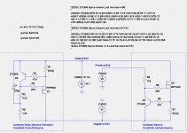
I have a question about the choice of constant current source (CCS) for the XA.8 amplifiers. Here I compare two circuits for a CCS on the negative rail:
My question is whether there is some reason not to use circuit 2, the common source CCS. The only downside I can imagine is PCB layout considerations might make it difficult to reach the positive rail.
I have a question about the choice of constant current source (CCS) for the XA.8 amplifiers. Here I compare two circuits for a CCS on the negative rail:
- Left: Common Drain (Source Follower) similar to that used in the Aleph.
- Right: Common Source.
My question is whether there is some reason not to use circuit 2, the common source CCS. The only downside I can imagine is PCB layout considerations might make it difficult to reach the positive rail.
Attachments
put cap C-E , then there is no diff

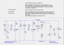
The middle circuit is your recommendation (I think), but it has relatively poor performance in comparison.
Attachments
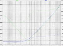
Have you played with the value of the capacitor in the bootstrapped version?
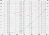
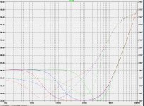
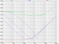
Here is the bode plot of the middle circuit (ZenMod's version) with 10uf, 220uf and 1000uf bootstrap cap.
Attachments
try it on your original bootstrap circuit as well
At your request. As a practical matter, a cap larger than 220uf takes too much PCB space.
Attachments
Simple is better, then. Why add another possible point that needs tweaking. Maddening prospect, if you ask me. Its easy to make things more complicated. Check out the CFA vs VFA thread. Too many junctions kill music. Its like taking an original recording and making a copy, then a copy of the copy, then a copy, of the copy, of the copy, and so on. Balance between need and numbers. One of the many lessons i think Nelson has tried to pass on. Always a possibility i am misguided. It does seem to be a trait of mine
Last edited:
- Status
- Not open for further replies.
- Home
- Amplifiers
- Pass Labs
- XA.8 single-ended current sources