specifically - post #45
at least in my FF (even if I have set famous 50 posts per page) direct links to post are always shabby
at least in my FF (even if I have set famous 50 posts per page) direct links to post are always shabby
Very nice job, I am flattered.
The X1000 actually has 80 output devices per channel,
not 16, and the input devices (IRF610)are also
cascoded to keep the dissipation down on them.
Hello to everyone.
I am trying to build myself a copy of X250.8. I hope, that it is not a problem. I am using the old published schematics from the other projects, which Nelson Pass made free on the internet, together with the specifications of the X amplifiers and pictures of the amplifiers from the net. For the moment, I believe that I managed to reproduce, to some extent, the circuit. However, I cannot understand the following: in the attached picture it looks like the 8.2k 3W resistors are the feedback resistors, but I cannot understand why they are 3W? Also, should they not be with accuracy greater that 5%?
If any one have some ideas I will be happy if he shares them.
Best Regards,
Adriyan
Attachments
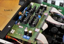
Feel free to match the resistors, we do even some of the1% types. The Panasonics actually are usually much better than 5%.

- Home
- Amplifiers
- Pass Labs
- X100 backengineered here