 Matching twins...
Ralf
Try this page http://www.diyaudio.com/forums/showthread.php?s=&threadid=6799
jh6you
Your understanding of CCS is in my opinion ok only as we are talking about one CCS or two closely conneced CCS at the tail.
Lack of matching (CCS or not) certainly rises the audiophile anxiety to a level worth a shrink, and by the way, I am a badly mached tween my self, I know all about it.
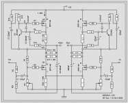
Here is XSOZV2 Revision 5.
The circuit is nothing more than re-drawing and minor correction of
misprint. Forgive me if I have broken the schematic drawing standard.
Thanks to Nelson Pass and Henrik, this project could be no-nonsense.
I started cutting steel for the materialization of this project.
And, acc. to the progress, I would try to post one or two pictures.
By the way, it is not too late. If any part of circuit looks something
wrong, I would much appreciate your kind indication.
Thanks.
🙂
Attachments
jh6You
You could consider the following setup:
Q1 and Q2 -> IRFP240
R4 -> 10k (adjusted to 6.2k)
R5 -> 6.8k
R8 -> 100 Ohm
C4 -> 220pF (no peaks in the corners at a 10 or 100 kHz square wave)
Leave out R21 and C2.
This setup should give You -3db low pass at 100kHz, and -0.15db at 20kHz.
I am using IRFP240 at the moment, an they sound very nice.
They have a lower Cgs, the reason for the much easier run to the 100kHz at -3db.
Can´t wait to hear, unfortunately not your amp, but then your description of its sound and some pics too.
🙂
I’ll try your resistors, capacitor and Q1&2, too.
The sound, the sound...yeah, I’m also excited,
wondering when I could finish the construction.
The speed of construction could be obtained by
three variables I have: workload, laziness and
wife’s mood.
😉
The sound, the sound...yeah, I’m also excited,
wondering when I could finish the construction.
The speed of construction could be obtained by
three variables I have: workload, laziness and
wife’s mood.
😉
Luckily, I got 20 x IRFP240.
I hope I could manage to get 2 x four matching fets among 20.
To find the matching sets, I will try as explained in
http://www.passdiy.com/howto.htm.
By the way, is there any idea to find the matching twins just by a look?
Or, what about if I use the gravity? I drop all 20 at the same time at
the 1m height, and select 8 that are touching the ground first.
 Those touching the ground first must be the fastes!
You only need to mach input Q´s as pairs, and CCS as separatley pairs.
Find 2*2 and 2*2 matching pairs.
No problem to find this among 20 pieces.
Find 2*2 and 2*2 matching pairs.
No problem to find this among 20 pieces.
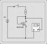
I wanted to find the matching pairs by the touching-ground-first
method. But, I found that the method in http://www.passdiy.com/howto.htm
was easier and more reliable.
I used 9V (battery) instead of 15V, and used 1k-R instead of 2.2k.
All pairs matched within 5mV. Average Vgs was about 3.25V.
I hope these are in order. Otherwise, pls correct me.
Attached is how I did.
Attachments
Keep in mind that matching the 240's at 5 mA is not
quite the same as matching them at an amp or so, if
that's where they are going to be operating.
Toward that end, I recommend maybe higher voltage and
less resistance. Say 15 volts and 10 ohms.
quite the same as matching them at an amp or so, if
that's where they are going to be operating.
Toward that end, I recommend maybe higher voltage and
less resistance. Say 15 volts and 10 ohms.
Where could I get the 15 volt DC supply...?
Could I use Zen as a tester?
If yes, I want to have the test where Q1 is, after cut it off.
It is a breeze because mine is made-up with p2p wiring.
Could I use Zen as a tester?
If yes, I want to have the test where Q1 is, after cut it off.
It is a breeze because mine is made-up with p2p wiring.
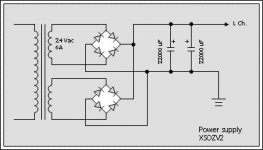
I will have two transformers for XSOZV2. The attached drawing
shows one channel power supply, with two bridges.
I know that there is interesting comparison of two bridges
with one bridge in another thread. It seems that two bridges
receive a prize. It is however applicable only for +/- polarities.
I wonder in case of one polarity... One better? Two just OK?
shows one channel power supply, with two bridges.
I know that there is interesting comparison of two bridges
with one bridge in another thread. It seems that two bridges
receive a prize. It is however applicable only for +/- polarities.
I wonder in case of one polarity... One better? Two just OK?
Attachments
I got 17V DC from my Zen amp. With the 17 volts and 10 ohms, I tested Vgs of 28 x IRFP240.Nelson Pass
Keep in mind that matching the 240's at 5 mA is not
quite the same as matching them at an amp or so, if
that's where they are going to be operating.
Toward that end, I recommend maybe higher voltage and
less resistance. Say 15 volts and 10 ohms.
Results:
* Min. Vgs 3.789V
* Max. Vgs 4.430V
* Avg. Vgs 4.072V
The values were found scattered. But, selection of matching pairs within 20mV was not a big deal.
Thanks.
PS
Phew... Handling steel is really hard work. I wish if I were living next to Peter Daniel.
jh6You
jh6You,
is your schematic a only computer simulated one? or do you have build a beta circuit and have you heard/compared it with the original SOZ? Can this circuit be connected to BoSoz without changing Bosoz?
Your circuit would be very intersting for me to build aktive speakers with 3 Amps per chanel (30 Watts per amp??). since it seames to be builded much cheper than SOZ. With original soz it would be too expensive for me, cause of the need of big parts for running and cooling it.
Regards,
Ralf
jh6you said:Here is XSOZV2 Revision 5.
The circuit is nothing more than re-drawing and minor correction of
misprint. Forgive me if I have broken the schematic drawing standard.
Thanks to Nelson Pass and Henrik, this project could be no-nonsense.
I started cutting steel for the materialization of this project.
And, acc. to the progress, I would try to post one or two pictures.
By the way, it is not too late. If any part of circuit looks something
wrong, I would much appreciate your kind indication.
Thanks.
🙂
jh6You,
is your schematic a only computer simulated one? or do you have build a beta circuit and have you heard/compared it with the original SOZ? Can this circuit be connected to BoSoz without changing Bosoz?
Your circuit would be very intersting for me to build aktive speakers with 3 Amps per chanel (30 Watts per amp??). since it seames to be builded much cheper than SOZ. With original soz it would be too expensive for me, cause of the need of big parts for running and cooling it.
Regards,
Ralf
Ralf
Yes, only computer simulated so far. I am building it now.
The part requiring most hard work is completed. I hope I could
have the final product soon.
Yes, you could use the original BOSOZ.
I will try to come up with few pictures and other interests.
Thanks.
Yes, only computer simulated so far. I am building it now.
The part requiring most hard work is completed. I hope I could
have the final product soon.
Yes, you could use the original BOSOZ.
I will try to come up with few pictures and other interests.
Thanks.
Ralf and jh6you
When I simulate XSOZV2 R5 and BSOZ, it seems as the BSOZ do have a hard job driving the XSOZV2 R5. To do this in the simulater, you have to do some change in the BSOZ, C1 an C2 must be 100uF and R15=24 Ohm (proberly means increaced distortion) to bring XSOZV2 R5 to full outputswing.
This is only simulation, so reality could be different.
Henrik and jh6you
Henrik and jh6you,
increasing capacity of the couple C`s and decreasing R15 should not be the problem...
Do you think distortion will increase though, when i have matched the Transistors of Bosoz?
If i would build the version of you. Henrik, i need to build new Bosoz (XBosoz), and i try to avoid this.
But at last i will build, what sounds best.
I hope jh6you will soooooon tell us somthing about the sound of his version.
jh6you, can you compare your version with the SOZ?
Regards,
Ralf
Henrik said:Ralf and jh6you
When I simulate XSOZV2 R5 and BSOZ, it seems as the BSOZ do have a hard job driving the XSOZV2 R5. To do this in the simulater, you have to do some change in the BSOZ, C1 an C2 must be 100uF and R15=24 Ohm (proberly means increaced distortion) to bring XSOZV2 R5 to full outputswing.
This is only simulation, so reality could be different.
Henrik and jh6you,
increasing capacity of the couple C`s and decreasing R15 should not be the problem...
Do you think distortion will increase though, when i have matched the Transistors of Bosoz?
If i would build the version of you. Henrik, i need to build new Bosoz (XBosoz), and i try to avoid this.
But at last i will build, what sounds best.
I hope jh6you will soooooon tell us somthing about the sound of his version.
jh6you, can you compare your version with the SOZ?
Regards,
Ralf
Ralf
Decreasing R15 will raise the amount of distortion, Nelson has described this in his papers on the BSOZ.
If You increase gain and distortion just for loosing the gain at the inputload at the poweramp, then the only thing You gets is distortion.
A better way is to lower the outputimpedance of the BSOZ, and a good way to do this is to make the X-feedback.
The X cancels more or less distortion from the gainprocess.
The lowered outputimpedance from the X circiut helps You loosing only a minor fraction of the gain at the load in the poweramp, even when it is as low as 200 Ohm. Actually the XBSOZ can drive a headphone at 60 Ohm.
I have almost finished my testsetup for 4 different variations of CCS´s for the XBSOZ, but I have to work hard these days to stay a live, but I hope that I will have some results next weekend.
Ralf
Please note that I have Zen V2 only for the time being.
XSOZV2 is my first X-fied diff pair amp.
I am fabricating it at maximum continuous revolution speed.
Expected launching is this weekend.
Henrik
Much interested in your four variations of CCS.
If you post the results, would be great for us.
All the best!
henrik and jh6you
"I am fabricating it at maximum continuous revolution speed.
Expected launching is this weekend."
I like those fanatics.....

Regards,
Ralf
"I am fabricating it at maximum continuous revolution speed.
Expected launching is this weekend."
I like those fanatics.....
Regards,
Ralf
- Home
- Amplifiers
- Pass Labs
- x soz