actually, now that I look at it, you should be able to get 35-40 watts out of it with a 3 amp current source on top and bottom (I doubled up the mosfets on the circuit above).
And... there is something wrong with the current sources- They seem to have 30 volts from G-S, which is obviously not a good thing. Any ideas?
And... there is something wrong with the current sources- They seem to have 30 volts from G-S, which is obviously not a good thing. Any ideas?
Grataku, It is my impressin that Simetrix is the easiest sim to use, its quick and reliable.
This link shoud do the trick for you: http://www.penzar.com/links.htm
And some more:
http://www.qsl.net/k7qo/models.htm
http://www.aplac.hut.fi/aplac/models/main.html
http://www.ee.washington.edu/circuit_archive/models/
http://www.svetlana.com/docs/products/spicemodel.html
If you can´t find what you are looking for, the I can e-mal you what you need if I have it on hand, I proberbely have.
Hi Steve!
I have just simulated your last scematic, it seems quite good.
If I were to build a new amp one of these days, I certainly would try the one of yours, I like it. But I am out of time for DIY at the moment.
I have attaced the scematic I have simulated, and the Simetrix file in the next post.
I have just simulated your last scematic, it seems quite good.
If I were to build a new amp one of these days, I certainly would try the one of yours, I like it. But I am out of time for DIY at the moment.
I have attaced the scematic I have simulated, and the Simetrix file in the next post.
Attachments
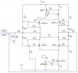
Thanks, Henrik for cleaning up the schematic, and simulating it. I'm glad you liked it! I will look over what you have there. I didn't have the gate resistors because I was limited to 50 components total (frustrating!) These are the first to go when I don't have enough to work with.
One thing I noticed- you changed the value of the bias resistors. I had the pots on the bottom ones because it was a way to adjust for overall DC offset, and guarantee maximum voltage swing, both positive and negative. Did you find this to not be needed? Just curious.
One thing I noticed- you changed the value of the bias resistors. I had the pots on the bottom ones because it was a way to adjust for overall DC offset, and guarantee maximum voltage swing, both positive and negative. Did you find this to not be needed? Just curious.
Hi Hugo, thanks for the nice comment.
Steve
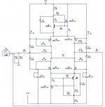
I changed the resistors R16-R3-R4 and R14 (partnumbers from my scematic) to get a little more voltageswing, that´s all, and I think it will be an good idea to start this monster off with some trimpots as replacement for those resistors, all of them, so you can determine how small they can be by listeningtest, because if the voltage across the CCS´s is too small you loose the X, and at the other side, if its too high you looses some voltage swing at the output. My guess is, that 6V across the CCS´s will do, but I am far from shure. When you have determined the voltage across the CCS´s and DC-offset then change the pots with resistors.
But with R16-R3-R4 and R14 at around 24K you need 3 Amp bias current to drive it to full swing with a load at 8 Ohm, therefore you need biasresistors at 0.15 Ohm since you have around 0.45V across them.
But do some serious ivestigations on the different posibilities to optimice this circiut, and also use irfp240 because of the lower inputcapacitance, if you use irfp140 the beast will be down 3db at 55 Hz or so, and that is too earley, it should make it to at least 90-100Khz. And dont use too high value for gate resistors, not more than 100 Ohm, also due to the inputcapacitance of the fets.
You should try the Simetrix simulator, its easey and there are some very high limit in the numer of parts to use as long as you go descrete.
I hope you will go for this one, and I am eager to read about it.
Regards Henrik.
Steve
I changed the resistors R16-R3-R4 and R14 (partnumbers from my scematic) to get a little more voltageswing, that´s all, and I think it will be an good idea to start this monster off with some trimpots as replacement for those resistors, all of them, so you can determine how small they can be by listeningtest, because if the voltage across the CCS´s is too small you loose the X, and at the other side, if its too high you looses some voltage swing at the output. My guess is, that 6V across the CCS´s will do, but I am far from shure. When you have determined the voltage across the CCS´s and DC-offset then change the pots with resistors.
But with R16-R3-R4 and R14 at around 24K you need 3 Amp bias current to drive it to full swing with a load at 8 Ohm, therefore you need biasresistors at 0.15 Ohm since you have around 0.45V across them.
But do some serious ivestigations on the different posibilities to optimice this circiut, and also use irfp240 because of the lower inputcapacitance, if you use irfp140 the beast will be down 3db at 55 Hz or so, and that is too earley, it should make it to at least 90-100Khz. And dont use too high value for gate resistors, not more than 100 Ohm, also due to the inputcapacitance of the fets.
You should try the Simetrix simulator, its easey and there are some very high limit in the numer of parts to use as long as you go descrete.
I hope you will go for this one, and I am eager to read about it.
Regards Henrik.
I don't think any resistor is necessary between the Sources.nobody special said:
need to be low value resistors between the sources?
I however would give my consideration to the Source resistors with greater than 0.22--e.g. about 3. (as I have applied for XSOZV2.)

Hi JH, you are right.
By the way I wrote: "if you use irfp140 the beast will be down 3db at 55 Hz or so" should have ben 55 KHz, sorry.
By the way I wrote: "if you use irfp140 the beast will be down 3db at 55 Hz or so" should have ben 55 KHz, sorry.
Henrik,
thank you very VERY much for the links!
and thank you for posting the simetrix files, it will start me off much higher on the learning curve!
thank you very VERY much for the links!
and thank you for posting the simetrix files, it will start me off much higher on the learning curve!
Thanks for the explanation, Henrik.
I don't know that I will build this one. There are a few things I don't like about it:
1. Low input impedance
2. capacitor coupling on the inputs
3. There seems to be a problem with the gain of the circuit varying with load impedance. Maybe the output impedance is high, or it is something with the feedback?
I am probably going to build something of my own design instead. I have a design that is class A push-pull, 2 gain stages (1 voltage, 1 current) that I want to try.
Grataku
Wish you good luck in the world of simulation!
Steve
About the things you don´t like:
1)
The low inputimpedance is a problem for most Zen´s and specially when you X them. But when you succed, keeping the frequensy responce within 1 to 100KHz at -3db and prober gain, the improvement is incredibel.
2)
It is my expierience, that the sins comitted by a gainstage is so much worse than those comitteded by a capacitor at the input. In the old days capacitors sounded realy bad, but to day they are so much better.
3)
The outputimpedance is quite high compared to many other amps, and it had become a kind of mantra, that low outputimpedance (high damping factor) is alway better, and that is´t true. I guess that many good sounding Valve amps has significant higer outputimpedance than the one in question here.
There is not such thing as the perfect amp, it´s all about compromises, and that is the personally choise that always should be respected.
You want to build a "class A push-pull, 2 gain stages (1 voltage, 1 current)", this sounds a bit more trivial to me, but I could be wrong.
Let us know what you are doing in the future and all the best.
Best regards.
Henrik said:
Wish you good luck in the world of simulation!
I'll need it!
I have already come to a grinding halt, I was able to load the zetex models no prob by just changing the filename.
However, the simple name change doesn't work for the irf files.
A few important models like the 240 and the 9610 are not part of the irf zip archive either.

Grataku, I could send you all models you need bay e-mail, and an instuction on how to install them.
What about that?
Just let me know.
What about that?
Just let me know.
I didn't try it in real life, but JH's schematic is exactly what Nelson meant to tell us.
It took me a long time to see my big mistake in connecting the source pins in the previous post: http://www.diyaudio.com/forums/showthread.php?postid=208216#post208216
I simply connected the gates instead of the sources.
Try it and let us know.
/Hugo 🙂
It took me a long time to see my big mistake in connecting the source pins in the previous post: http://www.diyaudio.com/forums/showthread.php?postid=208216#post208216
I simply connected the gates instead of the sources.
Try it and let us know.
/Hugo 🙂
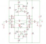
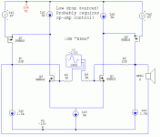
You can't get much XZen'er than this
I have been considering making a XZen myself for some time, but I have not been all that pleased with the basic Zen (for no better reason than I don't like the concept).
What I propose that you guys consider if you want to X the Zen is to simply build the input stage of the X and crank up the currents so that they are high enough to supply the load without output stage. This is what I have shown - a 9-10W into 8 Ohm XZen with total of 120W power dissipation. OK, so I went overboard with power, but bear in mind that this power is dissipated over mostly 7-8 transistors which is a great advantage over the original 1 transistor Zen.
You can of course mess around with input FET source degeneration, X resistor (which would give you 8 devices instead of 7 for most of the power dissipation) etc. Note, the unit is now drawn with classical long-tailed pair current source. No flames for that, please.
You can also increase efficiency by using bipolar transistors for current sources, or small sense resistors with op-amp feedback to reduce drop to a minimum. Using op-amps would certainly seem like a great idea to reduce power losses, particularly in top and bottom outer devices. You can also reduce power loss by adding another rail at say -5V for the bottom middle current source, thus saving 15W of power dissipation. Remember, you can drop less than one Vgs over a FET (reads current source) if you really want to.
Petter
Attachments
Henrik said:Grataku, I could send you all models you need bay e-mail, and an instuction on how to install them.
What about that?
Just let me know.
Where do you get the models? I've just downloaded the application, and seems to be great.
- Status
- Not open for further replies.
- Home
- Amplifiers
- Pass Labs
- X-ing Zen V5?