Thanks!
Those figures are low enough for me.. better start gathering some parts now... and match some of those MOSFETS.. I'll be using IRF510 and IRF9510 and I think I will use a lower supply voltage (+/- 30V ? ) ... I am still thinking about CCS for the Diff pair making the unbal to bal converter better.
Keep us informed!
🙂
gr,
Thijs
Thanks to your comment. jh6you.
I wonder the exact meaning of R&D, so I carefully read its description in an english dictionary.
I am thinking.
R&D looks like a desert without ending.
Invention looks like an oasis in a desert.
Patent looks like water in an oasis.
Drinking is free for traveller but seller.
B&D is a building for diys. 😀
stefanobilliani,
Ok, I'm hooked, but I'm a little slow. Could you possibly post your current schematic? I did a standard bosoz a few weeks ago, but I'm not altogether pleased with the construction. This is a great excuse for a re-do.
Charles bl
Also, thanks to Mr. Huang for starting this thread.
Ok, I'm hooked, but I'm a little slow. Could you possibly post your current schematic? I did a standard bosoz a few weeks ago, but I'm not altogether pleased with the construction. This is a great excuse for a re-do.
Charles bl
Also, thanks to Mr. Huang for starting this thread.
The mosfets are Irf 610 N channel, and
Irf 9610 P channel.
The trimmers are for regulation of output pins at O volt.
Irf 9610 P channel.
The trimmers are for regulation of output pins at O volt.


I lost the track in this thread. Is it the last and best sounding version? I'm just about ready to start building.😉
Freddie,
Thanks for clearing that up for me, (CCS =...). I'm a mechanical type so my acronyms don't translate, CVT = continuously variable transmission, IVT = ..., BS =..well that one probably does. Again, thanks, especially for not making me feel like an FI.
Charles BL
Thanks for clearing that up for me, (CCS =...). I'm a mechanical type so my acronyms don't translate, CVT = continuously variable transmission, IVT = ..., BS =..well that one probably does. Again, thanks, especially for not making me feel like an FI.
Charles BL
quiescent current
As I know, delta(Vgs) vs. delta(Id) would be more linear for higher quiescent current and then the distortion will be less. Of course, the supplied dc voltage determines the quiescent current.
How to determine the better or the best quiescent current under the constraint of supplied power? from datasheets of the mosfet, formula or by experiments?
Since I am a recruit in electronics, any suggestion will be appreciated.
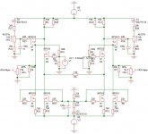
Since nobody answered my question about the optimal feedback and quiescent current until now, I would like to propose another upgrade of x-BOSOZ by adding temperature-compensated CCS (Constant Current Sources).
As mentioned early, this circuit does not need input and output capacitors by adjusting VR1 and VR2. However, in practical, the Vgs of Mosfet will be varied with the ambient temperature and Vsd. For small signal amplification, the temperature change dominates the variation of Vgs. In my opinion, stable quiescent current is quite important for this DC coupled circuit.
The temperature coefficient of zener diode depends on voltage and current. In addition, as zener voltage higher than 9V, its tempco is linearly proportional to voltage only.
Genius you can prove the CCS shown in the following circuit could be independent of the Vgs variation, if the tempco of zener is set to be about twice of the one of Mosfet. Note that the following drawing is just an example, and the selection of the voltage of Zener diode depends on practically measured tempco of the Mosfet. High value of current control resistor (750 Ohm) will help to reduce the influence of temperature change, too.
Any response will be appreciated.
Attachments
Even I have not test the early posted x-bosoz yet.
I still enjoy the sound of Audio Note Copper Pio cap., 10uf/300V, very big and quite expensive.
I had bought 30 pieces of IRF510 and I would try it latter.
The journey in desert could be quite long.
I am more interested in design and I hope somebody who had test the two circuits can describe the sound difference compared to the original bosoz in public and as detail as possible. When? A thanksgiving day for audio diy guys.
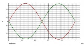
As attached is the simulation of the last posted circuit.
I still enjoy the sound of Audio Note Copper Pio cap., 10uf/300V, very big and quite expensive.
I had bought 30 pieces of IRF510 and I would try it latter.
The journey in desert could be quite long.
I am more interested in design and I hope somebody who had test the two circuits can describe the sound difference compared to the original bosoz in public and as detail as possible. When? A thanksgiving day for audio diy guys.
As attached is the simulation of the last posted circuit.
Attachments

- Status
- Not open for further replies.
- Home
- Amplifiers
- Pass Labs
- x-bosoz