My Fluke thermocouple says 72,4ºC (close to the mosfet)...I knew my fingertips were fairly accurate 😀
Arne K
Arne K
Henrik said:
No! Only the DC level at the drains.
Hi Henrik
You are right. Adjusting R101 and R102 affects the quiescent DC values, not bias current.
By the way, if I look into your amp, the so-called X-feedback controls the amp gain as well as lowers distortion and noise. In comparison, if I look into the Pass original design, R15 controls the amp gain as well as distortion and noise. Do you think the lowering distortion and noise with X-feedback is better than, instead, doing the same with R15? My question is with respect to the taste of the sound.
Regards
Henrik,
50°C is a good value when you dissipate around 20-30 watts in the fet. At 1.2 watt you can go a lot higher.
william
50°C is a good value when you dissipate around 20-30 watts in the fet. At 1.2 watt you can go a lot higher.
william
Hi JH6YOU
I haven´t tried to lower the gain by addig more feedback, but since the feedback is relatievly high, i suspect you might get too much, Nelson has stated that too much x-feedback tends to strain the sound.
Hi william!
Thanks for bringing this issue up.
Some years ago i e-mailed Nelson about the heat from my first bosoz, and he replied that i must have done something wrong since i wasn´t able to touch the small heatsinks that he suggests in his article. So since then i just followed "order".
So may be after all, the small heatsinks might be on the safe side.
If i am to take the consequense of the data sheets i gets the following results.
Tj => Junction tempreture in degrees C.
Ts => Sink tempreture in degrees C.
P => Power to dissipate in device.
Rjs => Termal resistance junction to sink.
Thus we have the equations: Tj=Ts+(P*Rjs) and Ts=Tj-(P*Rjs)
IRFP140:
Rjs=1.7
If Ts is 50 degree C and P=25W, then Tj=50+(25*1.7)=92 degree C.
Tj=92 degree C is acceptable as we accept Ts at 50 degree.
Now Irf610:
Rjs=4.0
If Tj=92 degree C and P=1.3W, then Ts=92-(1.3*4)=86.8 degree C.
Heatsink tempreture at 86.8 degree C for an IRF610 dissipating 1.3W is the logical consequence of the acceptance of an heatsinktempreture at 50 degree C for an IRFP140 dissipating 25W.
William, is this also how you see this?
Regards
I haven´t tried to lower the gain by addig more feedback, but since the feedback is relatievly high, i suspect you might get too much, Nelson has stated that too much x-feedback tends to strain the sound.
Hi william!
wuffwaff said:Henrik,
50°C is a good value when you dissipate around 20-30 watts in the fet. At 1.2 watt you can go a lot higher.
william
Thanks for bringing this issue up.
Some years ago i e-mailed Nelson about the heat from my first bosoz, and he replied that i must have done something wrong since i wasn´t able to touch the small heatsinks that he suggests in his article. So since then i just followed "order".
So may be after all, the small heatsinks might be on the safe side.
If i am to take the consequense of the data sheets i gets the following results.
Tj => Junction tempreture in degrees C.
Ts => Sink tempreture in degrees C.
P => Power to dissipate in device.
Rjs => Termal resistance junction to sink.
Thus we have the equations: Tj=Ts+(P*Rjs) and Ts=Tj-(P*Rjs)
IRFP140:
Rjs=1.7
If Ts is 50 degree C and P=25W, then Tj=50+(25*1.7)=92 degree C.
Tj=92 degree C is acceptable as we accept Ts at 50 degree.
Now Irf610:
Rjs=4.0
If Tj=92 degree C and P=1.3W, then Ts=92-(1.3*4)=86.8 degree C.
Heatsink tempreture at 86.8 degree C for an IRF610 dissipating 1.3W is the logical consequence of the acceptance of an heatsinktempreture at 50 degree C for an IRFP140 dissipating 25W.
William, is this also how you see this?
Regards

Thanx, Henrik!
Your last schematics gave me the change I needed, I'm probably too used to my BUF-04 + Dact pre-amp with no gain...😀
Arne K
Your last schematics gave me the change I needed, I'm probably too used to my BUF-04 + Dact pre-amp with no gain...😀
Arne K
Hi Arne
Glad you made it.
And may be your hot regulators are okay, i certainly have to get used to those tempretures.
Regards
Glad you made it.
And may be your hot regulators are okay, i certainly have to get used to those tempretures.
Regards
Hi Arne,
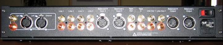
very nice! Can you tell a bit more about your output/input board (wich relais, source etc.).
What volume attenuator is that you use?
I like the front of your amp although I think it would be nice if the knobs were a bit bigger.
William
very nice! Can you tell a bit more about your output/input board (wich relais, source etc.).
What volume attenuator is that you use?
I like the front of your amp although I think it would be nice if the knobs were a bit bigger.
William
Thanx, all, particularly MAD_K, Henrik, Nelson Pass...
All controls are APOX; Front-panel w/remote sense, input boards, and "SHM" 20k volume boards.
http://www.apoxcontrols.com/apox.htm
Yes, I need new knobs, the ones I had did not fit the encoder-shaft.
Arne K
All controls are APOX; Front-panel w/remote sense, input boards, and "SHM" 20k volume boards.
http://www.apoxcontrols.com/apox.htm
Yes, I need new knobs, the ones I had did not fit the encoder-shaft.
Arne K

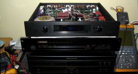
😀 Some of our scandinavian members may recognize the chassi from LC Audio...😉
(I do not think you get that sound-quality from that box normally...) 😎
It's not a Sidewinder anymore, I call it the "Conquest" !
Arne K
(I do not think you get that sound-quality from that box normally...) 😎
It's not a Sidewinder anymore, I call it the "Conquest" !
Arne K
Hi Arne!
It crossed my mind - it´s a nice case.
What happened to the sidewinder - and what is the difference in sound?
It crossed my mind - it´s a nice case.
What happened to the sidewinder - and what is the difference in sound?
Hi!
The sidewinder was never there! I was lucky getting a "one-off" chassi after they ended sale.
Have heard the sidewinder long ago, and actually wanted to buy/build one myself, but there was not enough inputs!!!
And I do not think/remember the Sidewinder beeing that musical, dynamic, with so much detail as the X -BOSOZ!
Arne K
cobra,
I was going to ask you about the transformer so close to the low level signal...no EMI problems? I had lots in my first BOSOZ.
Great job by the way,
I was going to ask you about the transformer so close to the low level signal...no EMI problems? I had lots in my first BOSOZ.
Great job by the way,
ccs'ed, cs'ed
Hi,
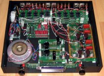
I finally managed to build myself a cs-ccs-x-bosoz as a drop in replacement for my "standard" x-bosoz.
The schamatic as along the lines of Metallman's version with a few simplyfications (only one voltage source for the gates of the cascode fets). No zener but blue leds (3 for the voltage source and 2 as a voltage ref. for the current source).
All fets are IRF610 (Harris) and only standard parts are used (an exception are the Black Gate N 47uF at the outputs)
Since it is a drop in replacement for the amp described earlier in this thread it will take +60V and +60V. You can see the 4 470 Ohm resistors forming one 470R/8watt resistor to relief the current source fet.
Instead of fitting the fets to the bottom of the case I have them attached to a piece of aluminium (10mm thick x 40mm high x 160mm wide) with some holes drilled in. This will be connected to the bottom of the case with two M4 screws
I only did some measurements until now and it seems to work fine. Bandwidth is over one MHz (around 1.4MHz) wich also explains the nice square wave at 10kHz😀 This is almost 10x that of my original x-bosoz.
William
Hi,
I finally managed to build myself a cs-ccs-x-bosoz as a drop in replacement for my "standard" x-bosoz.
The schamatic as along the lines of Metallman's version with a few simplyfications (only one voltage source for the gates of the cascode fets). No zener but blue leds (3 for the voltage source and 2 as a voltage ref. for the current source).
All fets are IRF610 (Harris) and only standard parts are used (an exception are the Black Gate N 47uF at the outputs)
Since it is a drop in replacement for the amp described earlier in this thread it will take +60V and +60V. You can see the 4 470 Ohm resistors forming one 470R/8watt resistor to relief the current source fet.
Instead of fitting the fets to the bottom of the case I have them attached to a piece of aluminium (10mm thick x 40mm high x 160mm wide) with some holes drilled in. This will be connected to the bottom of the case with two M4 screws
I only did some measurements until now and it seems to work fine. Bandwidth is over one MHz (around 1.4MHz) wich also explains the nice square wave at 10kHz😀 This is almost 10x that of my original x-bosoz.
William
Attachments
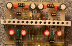
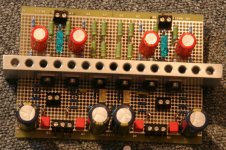
and another picture.
On top you can see the four output caps (no bypass yet) and the eight resistors from the current sources.
The lower part show the input fets and current source fets plus pots for the current setting (90mA per amp at the moment)
William
On top you can see the four output caps (no bypass yet) and the eight resistors from the current sources.
The lower part show the input fets and current source fets plus pots for the current setting (90mA per amp at the moment)
William
Attachments
- Status
- Not open for further replies.
- Home
- Amplifiers
- Pass Labs
- X-BOSOZ first tests