I would like to try and make a 1st order high pass filter for my X-BOSOZ by placing an inductor between the + and - balanced output leads after the blocking capacitors.
I need a high pass Fc of 120 Hz.
There must be a simple first order equation for inductors like the first order equation for capacitors and resistors?
Does anyone have a link to this information?
I have never used an inductor as a filter element, but I think it might work well as I only need 1 inductor per channel and the CMR will be equal for each channel.
I currently use the blocking capacitors as a 1st order high pass filter.
It's simple enough. Of course the output capacitors form such a filter, and with a coil you could have 2 poles if you want.
Assuming you don't, and that the caps are large values compared to the filter and that the load impedance is large compared to the output impedance of the circuit, the -3 dB point would be where the inductor's impedance is equal to the output impedance, which is
L = R / (6.28 * F) where inductance L is in Henries, frequency F is in Hertz, and output impedance R is in ohms.
For a BSOZ, the output impedance is the sum of the resistors going to the positive rail from the output. For example, two 750 ohm resistors for 1500 ohms.
The fly in the ointment comes from the feedback you apply to make it into an X circuit. This will lower the output impedance, and so you must measure it by seeing the output loss when the circuit is loaded resistively. The output impedance will be equal to the resistive load which drops the output voltage by half.
Yeah, the  Nelson is so right!
And my simulator agree too.
Ignatz
The outputimpedance of my version of the X-BOSOZ is 20 Ohm diffrential, and acording to NP´s formula you sould get a low end rolloff at 120 Hz with an inductor at 26mH, ok- my sim said about 24 mH. But acording to my simulator the outputcaps also plays a role, and with a value of around 2uF and a load at 20K balanced, you shoud get the most beautiful lowend roll off. I have also simulated 18uF outputcaps in combination with an 24mH inductor.
Nelson is so right!And my simulator agree too.
Ignatz
The outputimpedance of my version of the X-BOSOZ is 20 Ohm diffrential, and acording to NP´s formula you sould get a low end rolloff at 120 Hz with an inductor at 26mH, ok- my sim said about 24 mH. But acording to my simulator the outputcaps also plays a role, and with a value of around 2uF and a load at 20K balanced, you shoud get the most beautiful lowend roll off. I have also simulated 18uF outputcaps in combination with an 24mH inductor.
Attachments
Nelson & Henrik:
Thanks for the very detailed information.
I will make the changes this weekend assuming I can get the inductors tomorrow.
Thanks again to a great forum.
Thanks for the very detailed information.
I will make the changes this weekend assuming I can get the inductors tomorrow.
Thanks again to a great forum.
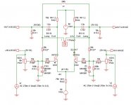
Ignatz said:I would like to try and make a 1st order high pass filter for my X-BOSOZ by placing an inductor between the + and - balanced output leads after the blocking capacitors.
The obvious question is why you want inductor, if the caps can form high pass filter? I assume you keep large value caps, so only the inductor acts as a first order filter.
Peter
I was wondering that too.
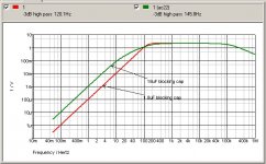
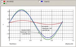
But when I saw the sim of the shape sf the roll off, it seemed to me that it looked much more like a 2´end order filter, with a much nicer cutoff.
The red curve is with inductor at 24mH and 2,2uF outputcaps.
The green curve is without inductor and outputcaps at 2.2nF.
What this means to the sound I don´t know, might depend on the drivers, but maybe Ignats will tell.
I was wondering that too.
But when I saw the sim of the shape sf the roll off, it seemed to me that it looked much more like a 2´end order filter, with a much nicer cutoff.
The red curve is with inductor at 24mH and 2,2uF outputcaps.
The green curve is without inductor and outputcaps at 2.2nF.
What this means to the sound I don´t know, might depend on the drivers, but maybe Ignats will tell.
Attachments
Reason for inductor
Peter & Henrik:
My original reason was just to see what it would sound like and to experiment with inductors, which I have never used before.
Using an inductor this way makes the common mode rejection of the filter matched perfectly for each channel.
My attenuator does the same thing. One resistor in the signal path for attenuation is hard to improve on.
One extra inductor in the signal path may diminish the sound quality?
The slope with the inductor (Henrik's simulation) more closely approximates the 2nd order Butterworth low pass filter to my subs.
My Gradient electronic cross-over uses a 2rd order Butterworth high pass, but it takes the magic out of the music so that is why I have been using a 1st order cap filter.
The cap filter takes a little of the low frequency load off the panels, but more would be much better.
Henrik's design may be an exellent match for my system.
I do not think the slight phase shift will be noticeable. I also get a phase shift with the low pass as well.
I hope to try Henrik's design this weekend and I will post my listening observations.
Phase shift
Henrik:
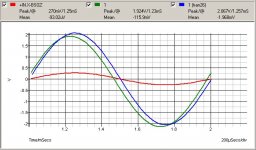
I just looked again at your phase shift plot.
The blue sine of the inductor appears to in phase with the input where it changes polarity.
The red sine of the cap looks like it is not in phase with the input.
Am I understanding your plot correctly?
Henrik:
I just looked again at your phase shift plot.
The blue sine of the inductor appears to in phase with the input where it changes polarity.
The red sine of the cap looks like it is not in phase with the input.
Am I understanding your plot correctly?
Re.😛hase shift
Hi Ignatz
I was a little too quick regarding my reasoning about the phase shift. You are right, the blue sine is made with inductor, not without, so my comments on plague an cholera was misplaced, the blue is almost in phase.
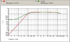
In my privious sine´s I had cap values at 2.2nF (no inductor) and 2.2uF (with inductor and low end cutoff down 3db at 116Hz).
The new sim is made with cap values at 1.8nF (no inductor) and 1.8uF (with inductor and low end cutoff down 3db at 120Hz).
Happy experiment on the filter.
Hi Ignatz
I was a little too quick regarding my reasoning about the phase shift. You are right, the blue sine is made with inductor, not without, so my comments on plague an cholera was misplaced, the blue is almost in phase.
In my privious sine´s I had cap values at 2.2nF (no inductor) and 2.2uF (with inductor and low end cutoff down 3db at 116Hz).
The new sim is made with cap values at 1.8nF (no inductor) and 1.8uF (with inductor and low end cutoff down 3db at 120Hz).
Happy experiment on the filter.
Attachments
JH, long time no se!
I think it is more like the DC-level which is maybe miscalculated, it is hard to tell. This is a simulator not a deasent scope like yours.
Congrats with your new monolitic X, great job.
I think it is more like the DC-level which is maybe miscalculated, it is hard to tell. This is a simulator not a deasent scope like yours.
Congrats with your new monolitic X, great job.
Henrik, I see a phase shift even in the second sim.
I got a lot of that in the AX when playing with the feedback caps.
Last night when I tried higher rails 19-0-19 I notice that things get considerably better, needs further testing...
I got a lot of that in the AX when playing with the feedback caps.
Last night when I tried higher rails 19-0-19 I notice that things get considerably better, needs further testing...
- Status
- Not open for further replies.
- Home
- Amplifiers
- Pass Labs
- X-BOSOZ 1st order inductor filter