Anyone know if this volume control is any good?
For $14 shipped, the price sure ain't bad.
I know you have to solder in 48 Rs but this is DIY after all.
Link -> http://www.diykits.com.hk/volume_control.htm
They also have a dual mono but any reason not so just use stereo? I figure sit in the middle if you want the speakers at the same volume.
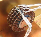
Here's a pic of the unit minus the Rs--
For $14 shipped, the price sure ain't bad.
I know you have to solder in 48 Rs but this is DIY after all.
Link -> http://www.diykits.com.hk/volume_control.htm
They also have a dual mono but any reason not so just use stereo? I figure sit in the middle if you want the speakers at the same volume.
Here's a pic of the unit minus the Rs--
An externally hosted image should be here but it was not working when we last tested it.
Hi,
re the switches alone I use them for two pairs of TX102 transformer volume controls They have replaced two Elma switches. I am very happy with them, they are very smooth which cannot be said of the Elma (which are also known to develop contact problems).
If you cannot afford Selden 😉 go for them! I cannot comment on the resistors but they look rather cheap.
g
Hi Giulio
can you tell how long you have been using your switch? I read some repports (I think from Peter Daniel) that those models also presented contact problems after a while. Peter Daniel was using the ready to use versions, built with Dale resistors.
Erik
can you tell how long you have been using your switch? I read some repports (I think from Peter Daniel) that those models also presented contact problems after a while. Peter Daniel was using the ready to use versions, built with Dale resistors.
Erik
I bought one of these through Ebay.
No soldering details were included and the seller said he did not have them.
http://cgi.ebay.co.uk/VOLUME-CONTRO...2254244QQihZ012QQcategoryZ64629QQcmdZViewItem
Now the listing says no manual etc.
So........Check first?
I also bought this - saves wiring but a little more money !!!
http://cgi.ebay.co.uk/ws/eBayISAPI....s=algo=SI&its=I%2BIA&itu=IA%2BUCI&otn=4&ps=42
Andy
poynton said:I bought one of these through Ebay.
No soldering details were included and the seller said he did not have them.
http://cgi.ebay.co.uk/VOLUME-CONTRO...2254244QQihZ012QQcategoryZ64629QQcmdZViewItem
Now the listing says no manual etc.
So........Check first?
I also bought this - saves wiring but a little more money !!!
http://cgi.ebay.co.uk/ws/eBayISAPI....s=algo=SI&its=I%2BIA&itu=IA%2BUCI&otn=4&ps=42
Andy
That's strange because I bought two, and while I would not say the provided diagram was all that clear I was able to figure it out. For $9 I have low expectations, they will either be used in infrequently used equipment and in an application where the level will be set and not frequently changed.
I figure the mediocre resistors are still likely to be better than the resistive elements in comparably priced pots.
I have several step attenuators with the elma switches and I have had some problems, all but one resolved by periodically tightening the screws that hold them together.
I bought one of these - and am pretty happy with it. Seems very neutral and the switch is reasonably smooth - although in my case I have a heavy knob on it which does make it smoother. Beats an alps pot anyway. This one is quite a low profile so is good for use in a tight spot. I just love the look of the "normal" ones with all the resistors though.
ebay link
So you pays yer money and you takes your chances.
Fran
ebay link
So you pays yer money and you takes your chances.
Fran
kevinkr said:
That's strange because I bought two, and while I would not say the provided diagram was all that clear I was able to figure it out.
Could you do me a favour and email me a copy of the diagram? (if you stil have it)
andydotathertonatyahoo.co.uk
thanks
andy
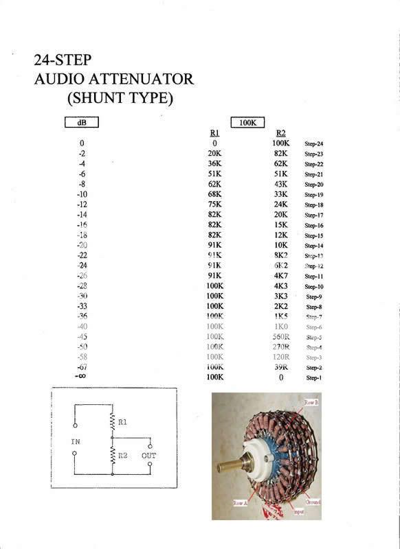
Shouldn't this chart give you the info you need? You might need to check which contacts are open/closed in a couple positions but once you know that, the list of R values should do it...
kvk said:Shouldn't this chart give you the info you need? You might need to check which contacts are open/closed in a couple positions but once you know that, the list of R values should do it...
Exactly what I have on paper, this is much better. Spliting the switch into two separate blocks of 4 rows you have the following:
The outer row is the input row, "R1" the next row has just two pins which can be tied together is the first wiper row the next row is the ground row, "R2" and the final row of 2 is the other wiper row.. The pattern then repeats.
The pins in row 1 & 3 that line up with the lefthandmost pins in rows 2 & 4 are the 0 position when switch is fully ccw. (Measure to confirm.) The two sets of wipers need to be connected together to work and this signal then goes to the input of the pre-amp or amp.
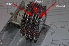
Note that there is a strong reflection off of the surface this attenuator was photographed on which makes it look like there is a fifth row of resistors - there isn't.
Incidentally there is another better way to do this if you think about it. Apply input to first wiper, wire R1 resistors from first to third row, and third row resistor R2 to ground buss. Take output off of wiper in row 4.. Instead of driving all of the contact capacitance, two sets of long wipers and all of the resistors simultaneously you drive just one resistor pair, this should lower input capacitance significantly. It will not look as nice and is harder to do as well.
kvk said:Shouldn't this chart give you the info you need? You might need to check which contacts are open/closed in a couple positions but once you know that, the list of R values should do it...
kevinkr said:
Exactly what I have on paper, this is much better. Spliting the switch into two separate blocks of 4 rows you have the following:
The outer row is the input row, "R1" the next row has just two pins which can be tied together is the first wiper row the next row is the ground row, "R2" and the final row of 2 is the other wiper row.. The pattern then repeats.
The pins in row 1 & 3 that line up with the lefthandmost pins in rows 2 & 4 are the 0 position when switch is fully ccw. (Measure to confirm.) The two sets of wipers need to be connected together to work and this signal then goes to the input of the pre-amp or amp.
Note that there is a strong reflection off of the surface this attenuator was photographed on which makes it look like there is a fifth row of resistors - there isn't.
Incidentally there is another better way to do this if you think about it. Apply input to first wiper, wire R1 resistors from first to third row, and third row resistor R2 to ground buss. Take output off of wiper in row 4.. Instead of driving all of the contact capacitance, two sets of long wipers and all of the resistors simultaneously you drive just one resistor pair, this should lower input capacitance significantly. It will not look as nice and is harder to do as well.
Thanks for the info guys !!!
Andy
Has anyone tested these volume control
I bought two of the 100K volume control as shown in kevinr's message. I tested them by feeding it with signal generator and see the output with an oscilloscope.
I was surprised that there were very high sharp spikes at the leading and falling edgies of the square wave at the output especially at low volume positions, lower the worse. I broke one in pieces to find out why that happens. May be it was caused by my test set up or may be it was caused by internal stray capacitance within the switch.
I have better success in building stepped volume control with resistors in series that I could see very favourable square wave response.
I just hope someone would test it and confirm my finding.
Johnny
I also have one of those attenuators as pictured in kvk's and Kevin's posting. I tried to measure this thing in order to find out how it is supposed to be wired up, but no real success yet.
Also not entirely clear to me...
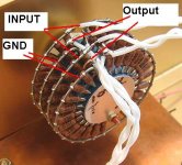
I also coincidentally found the pic attached (courtesy of triode dick's page)... so can anyone provide a simple schematic or description how it should be wired up?
thank you!
The pins in row 1 & 3 that line up with the lefthandmost pins in rows 2 & 4 are the 0 position when switch is fully ccw. (Measure to confirm.) The two sets of wipers need to be connected together to work and this signal then goes to the input of the pre-amp or amp.
Also not entirely clear to me...
I also coincidentally found the pic attached (courtesy of triode dick's page)... so can anyone provide a simple schematic or description how it should be wired up?
thank you!
Attachments
Hi Stixx
I edited your picture in paint. I think it is right, but it is easy to test. Put a DVM across the (marked) input and ground: this meter should read the pot's value (10k, 50k, 100k, whatever) in any position of the wiper. A second DVM is connected between the output and ground. This one should read low ohmic values for the low level settings, and increased values for the higher level settings.
Viel spass mit ausprobieren, und lassen Sie bitte wissen oder es funktionirt. (Good luck finding out, and please let us now if it worked)
Erik
Attachments
Viel spass mit ausprobieren, und lassen Sie bitte wissen oder es funktionirt. (Good luck finding out, and please let us now if it worked)
Hello Erik, dank u zeer, waardeer ik werkelijk uw hulp! (crude translation by babelfish...;-)
Thanks alot, I will try out... It is going to sit in my aikido headphone amplifier that I'm about to finish (breadboard version first). I'll post my impressions...
groet
(my boss is dutch but I'm hearing only the bad words in nederlands from him...;-)
OzMikeH said:
That rocks. Thanx for the post.
I compared the information with my stepped attenuator and found that two pairs of pins are connected as shown in OzMikeH's link.
When I measure across input and ground I am having 51K (both channels very exact), whereas across output and ground I am having ~0 - 36K...
So everything looks fine to me!
Thanks again Erik (and all the others...)!
When I measure across input and ground I am having 51K (both channels very exact), whereas across output and ground I am having ~0 - 36K...
So everything looks fine to me!
Thanks again Erik (and all the others...)!
Attachments
I bought a rottary switch with 24 steps like the one from from upper pics
now I have to get a resistors
can somebody recommend a place to purchase online good resistors
I need 20 K or 10 K attenuator
anybody tried the attenuator resistor set from thlaudio http://thlaudio.com/VishayDaleRmnE.htm
now I have to get a resistors
can somebody recommend a place to purchase online good resistors
I need 20 K or 10 K attenuator
anybody tried the attenuator resistor set from thlaudio http://thlaudio.com/VishayDaleRmnE.htm
- Status
- Not open for further replies.
- Home
- Design & Build
- Parts
- www.diykits.com.hk stepped volume control ... any good?