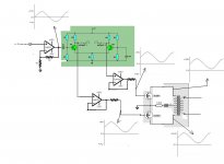
Hello all , I have made this design , for an high watts sine wave amplifier . I was wondering if diy members could help me critisize this deisng I wanna make and help .
The load on the secondary side is unspecified and unknown still , I dont expect much more than 2 amps @ a maximum of 50 volts , can be inductive or capacitive . It is not for audio .
I will be using only sine wave in the audio range .
Thx you
The load on the secondary side is unspecified and unknown still , I dont expect much more than 2 amps @ a maximum of 50 volts , can be inductive or capacitive . It is not for audio .
I will be using only sine wave in the audio range .
Thx you
Attachments
No it won't work... you have posted this circuit before 🙂
You are not understanding how to bias the FETs... as the gate voltage increases the FET is OFF untill the gate reaches the vgs threshold, at which point it will begin to conduct... and thereafter a small rise in vgs takes the FET from fully off to full on.
It's (the FET's) not working as a linear amp... just as a switch. They need either biasing correctly, and then "superimposing" your AC signal onto that, or incorporating into a feedback arrangement to stabilise the working point...
If you read some old books on early transistor amps you will see how transformers were used, usually with a complementary output pair PNP/NPN, but not always.
http://www.electronics-tutorials.ws/amplifier/amp_6.html
The main failing with your circuit is that the gates are not referenced to a common "point" for biasing... you will never get a stable bias point with an "open loop" output stage like this.
Last edited:
Hi Larry
I'm treating that circuit as a block diagram - indicative of a circuit rather than a refined design.
Load looks awkward driving a transformer like that with FETs - I would have probably opted for Ultra linear valve back end. What about back EMF effects from the load - is it mu core or laminated, what about maximum power transfer factor - no TX is 100% efficient, there will always be some residual energy - some given off as heat - some returned into the output stage if it cannot compensate? It would be an interesting reactive impedance to map out.
Hi Mooly
I'm not a FET guy as you probably read in a few threads in here -- but could op-amps with Offset adjust be able to force the correct forward Vgs - Would it also be dependent on Igs also? BJTs only need a few nA or in some cases μA -- it looks very crude.
I've started reading up on FETs and the big power ones are suggesting requiring mA not μA to push them well into enhancement mode
Not really... the offset null adjust operates over a narrow range and is used to zero out imbalances in the opamp... we are talking millivolts and less.
You could bias the opamps conventionally to give any desired output voltage as an "offset".
The problem is the FET, or BJT's if you used those. You take a power FET, find that it needs 4.00 volts vgs to begin to conduct. At 4.1volts the current flowing drain to source is rapidly increasing, the device is getting hot, that causes more current to flow as the vgs threshold is lower now it's hot, so you get thermal runaway. Exactly the same if a Bjt was used. 0.6 volts on the base and zero current flows, 0.65 and many amps flow. It's a knife edge with no mechanism to correct it.
The phase splitter in the green block is no good. At best, it will give square wave output.
Your previous circuit with op-amp phase splitter was much better. That just needed some DC offset to bias the mosfets.
The mosfets would be much happier with higher voltage and lower current though. e.g. Use a 50V rail instead of 13V.
If you fix this circuit so it works properly, it will still have very high distortion and high output impedance. Is that not important?
Why do you use an output transformer? Does the load have to be electrically isolated from the amp? If so, why not just use a normal audio amp and connect the load via a transformer?
Your previous circuit with op-amp phase splitter was much better. That just needed some DC offset to bias the mosfets.
The mosfets would be much happier with higher voltage and lower current though. e.g. Use a 50V rail instead of 13V.
What is it for?It is not for audio .
If you fix this circuit so it works properly, it will still have very high distortion and high output impedance. Is that not important?
Why do you use an output transformer? Does the load have to be electrically isolated from the amp? If so, why not just use a normal audio amp and connect the load via a transformer?
Not really... the offset null adjust operates over a narrow range and is used to zero out imbalances in the opamp... we are talking millivolts and less.
You could bias the opamps conventionally to give any desired output voltage as an "offset".
The problem is the FET, or BJT's if you used those. You take a power FET, find that it needs 4.00 volts vgs to begin to conduct. At 4.1volts the current flowing drain to source is rapidly increasing, the device is getting hot, that causes more current to flow as the vgs threshold is lower now it's hot, so you get thermal runaway. Exactly the same if a Bjt was used. 0.6 volts on the base and zero current flows, 0.65 and many amps flow. It's a knife edge with no mechanism to correct it.
So unless using opamp as a comparator (setting a ref V at one input leg) not much is going to happen in this circuit as there is no proper bias conditioning
So unless using opamp as a comparator (setting a ref V at one input leg) not much is going to happen in this circuit as there is no proper bias conditioning
Comparators are a bit different as they are really opamps used without feedback. The output just swings hard to the rails as the input passes through the ref voltage set on one of the inputs (in simple terms). Any opamp can be used as a comparator.
You can easily bias the opamp (in the above circuit) to give any desired offset at it's output and for it still to work as a linear amp. The problem is whatever you set it too is then way to critical to bias a transistor of any type when used in a common emmiter or common drain configuration.
So in this circuit even if you have a nice sinewave at the output of the opamp, the transistor only conducts when the vgs threshold is reached and it then just stays on until the signal falls again. For a push pull arrangement you need one transistor to take over as the other comes out of conduction, with a small bias current flowing to ensure freedom from crossover distortion... and that's where this falls down... you can not set that operating point with fixed voltages on the two gates that are independant of each other. It would be hugely critical on the slightest variation... even 1 or 2 degrees C change on the FET's would totally upset it.
yup - a bit of a pup
Hi Mooly
yeah - that's what I thought - the whole thing would end up being a heap of compromises
Larry - why this particular approach? tis a bit quirky
Hi Mooly
yeah - that's what I thought - the whole thing would end up being a heap of compromises
Larry - why this particular approach? tis a bit quirky
Last edited:
- Status
- Not open for further replies.
- Home
- Amplifiers
- Solid State
- Would this work , plz comment .