The PSU is designed for 350w and I would be at 360 with all six channels. I haven't built a GC yet but am trying to decide on what to do.
also what combo (bridge/Parallel) would be best for a 4 or 2 ohm load, I could wire a DVC woofer for 8 ohms though as power is power.
If I were to do 6 x 60 + 2 x300, would I just use 3 P89 supplies?
Would I be able to combine some parts of the supplies, as in using the 3525 to time all 3 SMPS'?
sorry for all the questions. I am able to build most projects, but haven't designed anything since school 14yrs ago.
I wasn't sure if it should go here or the PSU forum as it would still be a chip amp.
I wasn't sure if it should go here or the PSU forum as it would still be a chip amp.
I see your confusion of were to put it, you could of made two threads, one about the GC's and one about your PSU questions.
I can't answer your GC problems cause I have very little experince with them but I will give you a hand on the PSU.
If I were to do 6 x 60 + 2 x300, would I just use 3 P89 supplies?
Thats one option, or you could build one big one, or two smaller ones. One for the 6 x 60 and one for the 2 x 300.
Would I be able to combine some parts of the supplies, as in using the 3525 to time all 3 SMPS'?
Yes you can. All you have to do is have seperate drive transistor, mosfets, transformer, diodes and caps for them and a simple quad comparator for regulation. Doing it this way will aviod have mutiple switching frequencies.
If the power supply is designed for 350W output then it will not be enough for the amplifiers. These are Class AB so they are also using/burning power as well. You might want to look at the Design Guide National has on their web page and there is a graph in that guide (2nd tab) that shows power dissipation in the IC package vs. output power. If you add the power dissipation and the output power that is the peak power required from the supply for each IC.
For anything less than 4 ohms you want to use parallel or a bridge/parallel (BPA) combination. 4 ohms is OK for single-ended but once you want more power than the 50 - 60W then you will need to go parallel for 4 ohms or less. It comes out sixes on the DVC woofer. If you wire the VC in series to get 8 ohms then run in bridge mode you will end up with about 110W total output power. Or you can run each VC single-ended and end up with about 55W per voice coil. You might also want to build the 6x60W amp first and see how much power you really need. Many people get into the marketing mode that they NEED hundreds of watts but keep in mind that twice as loud (10dB more) is 10x the output power. So for that 60W to sound twice as loud requires 600W. 3dB louder is double the power.
-SL
Depends.
If you want to do bench testing with all channels at full power, probably not.
If you want to listen to music, more than enough. Music averages from less than a watt to a few watts per channel depending on your speakers.
If you power supply would be enough for all channels full power, your amps would probably die from heat stroke during bench testing at full power if you are not extremely careful.
Jan Didden
I see a EDT39 torrid core is recommended, and
Now if i were to use a EDT49-59 core and 12 0.4mm dia wires along with doubling the output MOSFETs in parallel would that double the current output as to be able to add more channels off of a single suppy? Or would I need to change the values of R1,R2,C1 and C2?
Just trying to see how I can follow the P89 project but put out more current.
six 0.4mm diameter wires can form a suitable primary for a 300W supply
Now if i were to use a EDT49-59 core and 12 0.4mm dia wires along with doubling the output MOSFETs in parallel would that double the current output as to be able to add more channels off of a single suppy? Or would I need to change the values of R1,R2,C1 and C2?
An externally hosted image should be here but it was not working when we last tested it.
Just trying to see how I can follow the P89 project but put out more current.
Or would I need to change the values of R1,R2,C1 and C2?
Do not change these values, they are the snubbers for the transfomer. Changing them will get you no extra power output.
Now if i were to use a EDT49-59 core and 12 0.4mm dia wires along with doubling the output MOSFETs in parallel would that double the current output
The core itself has a maximum power output, if you go pass that output the core saturates and you get a nice little space heater.
If you want to use one big core then you'll have to find one with a maximum output power higher than all your amps combined.
So unless you can get a very large transformer your stuck with several transformers.
What I need to do is to use the same circuit and get a tranformer(s) that can handle more amps and then extra MOSFETs to feed it?
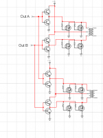
The brigde is rated at 35A and currently the supply is putting out 6 amps according to the article, iirc, so as long as the caps are rated 2x the voltage or so and I don't put out more than 30A I should be safe, correct? like this?
The brigde is rated at 35A and currently the supply is putting out 6 amps according to the article, iirc, so as long as the caps are rated 2x the voltage or so and I don't put out more than 30A I should be safe, correct? like this?
An externally hosted image should be here but it was not working when we last tested it.
It has to be like this to run multiply Xfrmr's.
Your first one is more efficent in terms of wasted power as heat.
your second one wound never work, one transformer will short out the other.
Each transformer must have it's own drive transistor, power mosfets, transformer and snubbers, and output rectifier. But after that they could (can) share the rest if both transformers are identical.
Attachments
ifrythings said:
The core itself has a maximum power output, if you go pass that output the core saturates and you get a nice little space heater.
If you want to use one big core then you'll have to find one with a maximum output power higher than all your amps combined.
So unless you can get a very large transformer your stuck with several transformers.
Actually, in push-pull-topology, the maximum power is dictated by winding resistance and thermal resistance, which determine how much heat can be dissipated without burning up the windings. Core flux density does not depend upon load current in "forward"-type topologies, like push-pull, forward, half- or full-bridge. The flux density is set by voltage-seconds in primary winding and core area, Ae.
Of course, there is a practical limit how hefty windings one can wind in specific core, so there is "core power limit".
I wouldn't recommend paralleling too many mosfets without checking the implications from driver circuit, the switching may become too slow. If more current is required, then I would change to better mosfet instead. That tends to create fewer problems.
Some interesting pages from "Fundamentals of power electronics":
Page 1 Page 2 Page 3
Regards,
Janne
- Status
- Not open for further replies.
- Home
- Amplifiers
- Power Supplies
- Would the P89 ESP SMPS be enough to power a 6 x 60w LM4780 amp?