Hi all. Build of my phono amp is now complete and I'm drawing up a set of tests to work through;
1) unpowered connectivity tests
2) powered, switched off
3) powered, heaters only
4) powered, heaters plus HT
I've built a series lamp limiter along these lines and tested that too.
http://golbornevintageradio.co.uk/forum/attachment.php?aid=12296
I've calculated my expected current draw as follows and would be really grateful if someone could check me (first real build).
HEATERS:
4 valves (2 x 12ax7, 2 x 6922) drawing 300mA each = 1.2A total
Transformer secondary is 9V x 1.2A = 10.8 VA
Transformer primary is 240V : so expect (10.8/240) = 45mA draw
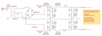
HT: Diagram attached if clarification is needed
B+ and B- each drawing approx 35mA (valves plus bleeders) total of 70mA
Transformer secondary is 300 - 0 - 300
70 x 300 = 21 VA
Primary is 240V : so expect (21 / 240) = 87.5mA
So in total I'm expecting a current draw of around 135mA ish
A 60W bulb will draw 250mA, so if all is well the bulb should see around 50% of it's rating.
I've no idea how much the draw has to drop through a bulb before it dims - but I did test the limiter using a bedside lamp with an identical 60W bulb and they both dimmed. Under those circumstances I'd expect the voltage drop over each to be about half. Since a bulb's resistance will vary with temperature I guess that doesn't mean each lamp had 125mA going through it. I guess I could always measure it !
1) unpowered connectivity tests
2) powered, switched off
3) powered, heaters only
4) powered, heaters plus HT
I've built a series lamp limiter along these lines and tested that too.
http://golbornevintageradio.co.uk/forum/attachment.php?aid=12296
I've calculated my expected current draw as follows and would be really grateful if someone could check me (first real build).
HEATERS:
4 valves (2 x 12ax7, 2 x 6922) drawing 300mA each = 1.2A total
Transformer secondary is 9V x 1.2A = 10.8 VA
Transformer primary is 240V : so expect (10.8/240) = 45mA draw
HT: Diagram attached if clarification is needed
B+ and B- each drawing approx 35mA (valves plus bleeders) total of 70mA
Transformer secondary is 300 - 0 - 300
70 x 300 = 21 VA
Primary is 240V : so expect (21 / 240) = 87.5mA
So in total I'm expecting a current draw of around 135mA ish
A 60W bulb will draw 250mA, so if all is well the bulb should see around 50% of it's rating.
I've no idea how much the draw has to drop through a bulb before it dims - but I did test the limiter using a bedside lamp with an identical 60W bulb and they both dimmed. Under those circumstances I'd expect the voltage drop over each to be about half. Since a bulb's resistance will vary with temperature I guess that doesn't mean each lamp had 125mA going through it. I guess I could always measure it !
Attachments
Last edited by a moderator:

what is the total VA of the XFMRs connected? I'd use overrated transformer windings esp on filaments.
the dim bulb is only used for current limiting under fault conditions , not operational duty. once normal operation is confirmed override the bulb. more or less a 75-100W bulb works for most needs.
I'm no expert in current fed HV supplies but they need constant load current under all conditions or they may go south in a hurry. isn't there a late /early start up /off sequence for them?
Last edited:
Your 0u22F||220r network between Chassis and Power Ground will not pass a Mains fault current.
imagine a 1000Apk fault current trying to pass from Power Ground to PE to blow your mains fuse.
What effect will your network have?
Why have you specified 12W? What's wrong with ¼W?
imagine a 1000Apk fault current trying to pass from Power Ground to PE to blow your mains fuse.
What effect will your network have?
Why have you specified 12W? What's wrong with ¼W?
Your 0u22F||220r network between Chassis and Power Ground will not pass a Mains fault current.
imagine a 1000Apk fault current trying to pass from Power Ground to PE to blow your mains fuse.
What effect will your network have?
Why have you specified 12W? What's wrong with ¼W?
I put that network there as I drain several shields to earth and didn't want that noise going to HT/signal ground. I specified a high wattage because I wanted to make sure a small value resistor wouldn't burn out if the worst happened. I picked up the values from research, but thinking them through surely higher wattage is better there ?
Shorts to the chassis bypass that network.
Shorts to HT/Signal ground (mains transformer centre tap) would go via that network. Say for example the mains transformer shorted putting 300VAC (RMS) to HT ground. 300v / 200R = 1.3amps. That's 409watts. hmmm - however why is it made better by using 1 quarter watt ? In this scenario either;
1) the primary fuse on the transformer would blow (1.3 amps on a 300V secondary / 240 = 1.7 amps on primary - the fuse there is 250mA)
2) the resistor would fry leaving no path to earth
What's the right answer for this ? Remove the network and not worry about shield RFI noise getting to ground ?
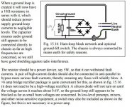
I quite like the explanations given by this guy ...
http://www.valvewizard.co.uk/Grounding.pdf
but re-reading that I notice that he also includes high-current diodes in anti-parallel "to
bypass more serious fault currents, thereby ensuring any fuses will reliably blow".
http://www.valvewizard.co.uk/Grounding.pdf
but re-reading that I notice that he also includes high-current diodes in anti-parallel "to
bypass more serious fault currents, thereby ensuring any fuses will reliably blow".
Attachments
Last edited:
The requirement is to protect the Chassis by making a direct connection from chassis to Protective Earth.
A subsidiary requirement is that all exposed metal, or conductive, parts should be connected to the Protected Chassis.
Take your RCA barrels as an example.
If some catastrophic failure allowed a mains wire to touch the RCA from the inside, or down the interconnect from a faulty double insulated item, then that mains will make much of the audio circuits LIVE.
Touch any part of those audio circuits, maybe the speaker lead, or another RCA barrel, and you get shocked.
Take the fault to Chassis and the Protective Earth will blow the mains fuse.
BUT !!! you have put in there a fusible link (220r 12W) that will not pass the 1000s of Amperes of fault current that will normaly blow the mains fuse very quickly.
You must provide a path for the fault current to get to the chassis.
Do more research. The answers are all in this Forum, but I'll point you to my posts, or to ESP, (he copied the Forum's ideas).
The resistor does not benefit from being rated at watts, a few tenths of a watt is enough to take interfence current (micro-amperes or nano-amperes) to chassis.
The resistor dissipation during a fault incident is predicted with the formula P=V²/R
for 240Vac and 220r you get 261.82W
If you use a more normal value from 1r0 to 22r then a 10r would be required to dissipate 5.76kW and would pass ~26Aac.
How quickly would the mains fuse rupture while passing that very hot 5.76kW resistor?
What voltage would be across the internal and exposed conductive parts while you wait for the mains fuse to blow?
There is a further requirement (at least in the UK) that the voltage on the exposed parts must not exceed some preset value during the fault incident. (I seem to remember that in the UK that value is 50Vac)
This is normally designed into the house cabling and determines the maximum resistance between the fault touching point and the Distribution board via the Protective Earth wiring.
Your 220r is inside that route. It will fail that requirement !
If you decide to go a different way with protecting the users of your mains powered equipment, then it is incumbent on you to research the risks and find methods to reduce those risks. Or you go to jail when you kill someone.
Last edited:
The requirement is to protect the Chassis by making a direct connection from chassis to Protective Earth.
A subsidiary requirement is that all exposed metal, or conductive, parts should be connected to the Protected Chassis.
Take your RCA barrels as an example.
If some catastrophic failure allowed a mains wire to touch the RCA from the inside, or down the interconnect from a faulty double insulated item, then that mains will make much of the audio circuits LIVE.
Touch any part of those audio circuits, maybe the speaker lead, or another RCA barrel, and you get shocked.
Take the fault to Chassis and the Protective Earth will blow the mains fuse.
BUT !!! you have put in there a fusible link (220r 12W) that will not pass the 1000s of Amperes of fault current that will normaly blow the mains fuse very quickly.
You must provide a path for the fault current to get to the chassis.
Do more research. The answers are all in this Forum, but I'll point you to my posts, or to ESP, (he copied the Forum's ideas).
The resistor does not benefit from being rated at watts, a few tenths of a watt is enough to take interfence current (micro-amperes or nano-amperes) to chassis.
The resistor dissipation during a fault incident is predicted with the formula P=V²/R
for 240Vac and 220r you get 261.82W
If you use a more normal value from 1r0 to 22r then a 10r would be required to dissipate 5.76kW and would pass ~26Aac.
How quickly would the mains fuse rupture while passing that very hot 5.76kW resistor?
What voltage would be across the internal and exposed conductive parts while you wait for the mains fuse to blow?
There is a further requirement (at least in the UK) that the voltage on the exposed parts must not exceed some preset value during the fault incident. (I seem to remember that in the UK that value is 50Vac)
This is normally designed into the house cabling and determines the maximum resistance between the fault touching point and the Distribution board via the Protective Earth wiring.
Your 220r is inside that route. It will fail that requirement !
If you decide to go a different way with protecting the users of your mains powered equipment, then it is incumbent on you to research the risks and find methods to reduce those risks. Or you go to jail when you kill someone.
Ok thanks Andrew. I'll remove the network and research more. I'm sure I've seen that this is common practise, but I can't fault your logic and learning from others is what this forum is for after all.
There is a further requirement (at least in the UK) that the voltage on the exposed parts must not exceed some preset value during the fault incident. (I seem to remember that in the UK that value is 50Vac)
This is normally designed into the house cabling and determines the maximum resistance between the fault touching point and the Distribution board via the Protective Earth wiring.
If this was true then power cables would require 4 times more cross section of earth wire than the others. 50 V limit applies to continuous or long term fault state. For short time (100 ms as I remember) there is no additional limit. So if breaker act faster then this, then it's OK. IMHO if every part connected to this signal GND are isolated from live voltage as much as needed for class II, then no need for PE connection. Maybe the idiotic rules not allow mixing Class I and Class II, but in reality everybody do this at home when building audio systems.
- Status
- Not open for further replies.
- Home
- Amplifiers
- Power Supplies
- Would someone please sense check my calcs ?