I've changed this to simple resistive (27k) cathode loads. I'm afraid of breaching the maximum grid-cathode resistance requirements of the EL34s. I wondered why I'd never seen a design using CCS-loaded directly-coupled cathode-follower drivers and that could be the reason, I'm not sure.Stage 3: 6SN7 PP cathode followers, with negative grid bias and a cascoded transistor CCS as the cathode load to the negative line of -115v for each triode.
316a said:
...not if the output transformer is specified as per the design . Split bobbin=good balance , the Partridge WWFB used in the design is excellent , almost faultless in fact
cheers
316a
It is impossible to make a tranny better balanced than a phase splitter. It is impossible to match output toobs better than you can design your phase splitter.
I tried VN2222 instead of a tail resistor (mine looks like a sister of famous Altec 1568, with Concrtina + diff cascade after it, similar to Williamson't design, but DC coupled for better stability on low end, and different spreading of amplification between stages, but the principle is still the same);
also I tried cascoded BJT current source for a tail; no sonic improvement at all;
results are even worse (also dynamic resistance of CCS is more frequency dependent than a plain resistor has).
In turn, when I suddenly ovedbiased an amp so one shoulder turned in something like a current source (red anode caused gas, gas caused grid current resulting in -1V bias) surprisingly the amp sounded much better than a true push - pull amp.
According to my experience push-pull amps have only 2 advantages: power consumption efficiency and low overall THD that is good for economical and marketing purposes, but specter of added harmonics makes the sound perceived as more distorted than sound of single - ended amp with much higher level of overall THD.
When THD raises with loudness close to what happens in mechanical media like decks of musical instruments, throats of singers, air, reflecting surfaces, human ears, such distortions are ignored by human perception: during the evolution we learned to ignore such distortions, like we ignore distortions of infra - red and ultra - violet rays looking at paintings of Leonardo.
The more added distortions differ from "natural" colorations caused by mechanical media, the more they are audible, even when measured much better. Examples of such bad things are: spectral difference at all and different change of specter with loudness (static and dynamic differences). That's why single ended triodes sound so good for hearing. They sound less distorted.
According to my experience push-pull amps have only 2 advantages: power consumption efficiency and low overall THD that is good for economical and marketing purposes, but specter of added harmonics makes the sound perceived as more distorted than sound of single - ended amp with much higher level of overall THD.
Was your experience with PP Class A triode. This is the only really fair comparison.
Shoog
Shoog said:
Was your experience with PP Class A triode. This is the only really fair comparison.
Any comparison is fair if you use your (or better your pet's!) perceptions as a measurement instrument. If a sound can scary you suddenly, or lead to another reactions of autonomous nervous system, it is better sound than when you consciously think that it is good sound and you love it. I prefer blind tests, when people don't know that they are testing an electronics equipment. If somebody is asking, "Hey, some water is leaking", or "who is playing piano in your house?", it is much-much better indicator than when audiogurus seat down comfortable and make smart faces... And no doubt much-much-much better than when somebody says drooling: "Oh, it uses XXX tubes and YYY topology, it sounds incredible!"
I agree with you, but its still a fair request to know if you were comparing apples with pinapples.
Shoog
Shoog
On further consideration I have to agree with Wavebourn on one crucial issue. I have rarely met anyone who doesn't prefer an amp with a small element of 2nd harmonic distortion over one with none. It is also my experience that a lot of people like a little bit of top end roll off. Both of these things an SE can do well be its very nature.
I still think that a well designed PP amp using class A triodes, Interstage Transformers, differential front to back, and zero overall feedback - can sound every bit as good as an SE, and its is my belief that they can sound better in one or two crucial departments.
Shoog
I still think that a well designed PP amp using class A triodes, Interstage Transformers, differential front to back, and zero overall feedback - can sound every bit as good as an SE, and its is my belief that they can sound better in one or two crucial departments.
Shoog
I have rarely met anyone who doesn't prefer an amp with a small element of 2nd harmonic distortion over one with none.
Meet me. I don't want my amp to be an effects box, its job is to replicate the input.
Me too. I'm not exactly in possession of golden ears but (as some website put it perfectly) adding of 'richness' or whatever you get from 2nd order harmonics isn't a desired effect! An amp should be as close as possible like a lens - totally clear and flawless as possible, as opposed to a coloured filter or a fairground mirror that makes you look really skinny!
(Admittedly using inherently imperfect components makes this a bit of a lofty goal 😀)
(Admittedly using inherently imperfect components makes this a bit of a lofty goal 😀)
Shoog said:I agree with you, but its still a fair request to know if you were comparing apples with pinapples.
Shoog
No way. I've compared subconscious reactions caused by sound and sound only, no matter what is inside of amplifiers: apples, pinapples, cats, rats... I even played with a "distortion masking" thing made of operational amps and diodes. When I "corrected" specter of distortions adding more of them, but more "naturally" curved, the impression was as if there are less of them. However, I could not mask one thing using such a trick: increase of distortions with wider spector on decay because it is impossible to "correct", they need to be minimized by design (like cleaning instead of repainting).
Also, "masking" works perfect on simple material, but does not work with orchestras due to increased intermodulations. That's why I always hear a solo saxophone and / or single female voice in "Hi end" stores, it is a cheap cheating trick to impress buyers...
My opinion is, that the amp should be as clean as possible, no matter has it FET switches or fat triodes inside, but measurements of "clearness" has to be made with understanding of human perceptions in mind, because any design is always an equation with many parameters, so optimizing some of them we may overlook others that spoil the whole picture.
Like, in order to tune a grand piano using a laser pointer to align strings perfectly horizontally...
Meet me. I don't want my amp to be an effects box, its job is to replicate the input.
I haven't met you yet😀
I would never design distortion in. It was simply an observation that when a bit of second harmonic was there it generally produces a favourable response in many listeners.
People often say they want less distortion, but often the reality seems to be that this is only up to a point.
Shoog
Beware the false dilemma as well. The SE headphone amp on my bench swings ~105dB at approximately 0.03% 2nd and ~0.003% third. This SE doesn't sweeten.
Shoog said:simply an observation that when a bit of second harmonic was there it generally produces a favourable response in many listeners.
Could it be the lack of crossover distortion or flux reversal, and just fortunate that 2ndHD is relatively benign?
Shoog said:
I haven't met you yet😀
I would never design distortion in. It was simply an observation that when a bit of second harmonic was there it generally produces a favourable response in many listeners.
People often say they want less distortion, but often the reality seems to be that this is only up to a point.
Yes!
They want less distortions of reality, but not of some easily measured parameters of electric signal.
An example: if a snake is just hanging on a branch of a tree you don't pay attention. But if a peace of a rope slips down from the same branch you would be scared, right? Does it mean that you love a snake, but hate a rope?
The same with audio distortions. If they mimic what you (and many generations of living creatures) used to hear during an evolution you don't hear them. But when they add a difference from what we used to perceive in a real world no doubt they will be spotted even if they are invisible on your smart electrical toy.
People don't love a second harmonic; you repeat some silly opinion spreaded around by people who religiously believe in measurements that are accepted as standards; they simply want to explain why listeners don't like what they believe is the best; the simplest way for profanes is to blame on listeners instead of trying to understand why it happened such a way, why people don't like "a perfectly measured amplifier".
jnb said:
Could it be the lack of crossover distortion or flux reversal, and just fortunate that 2ndHD is relatively benign?
I totally agree with you. Crossover distortions are the worst by-product of an industry that is running in the wrong direction sincd 1960'th when people found a new way to make money selling transistor amps.
I think one can be misled by the term High Fidelity (HiFi). Those who truly like HiFi believe that an amp has no business changing the signal any more than can be avoided. They consider any form of distortion to be a failing.
People who prefer the sound of SE don't, in fact, like HiFi. Instead, they like the signal to be enhanced in a subtle way that sounds richer to their ears.
Who is to say which opinion is correct?
"There are HiFi amps and there are SET amps but there are no HiFi SET amps." - Anon
People who prefer the sound of SE don't, in fact, like HiFi. Instead, they like the signal to be enhanced in a subtle way that sounds richer to their ears.
Who is to say which opinion is correct?
"There are HiFi amps and there are SET amps but there are no HiFi SET amps." - Anon
Sorry to jump back in the thread but I really would like to understand the issue with CCS at both plate and cathode in a LTP.
Please explain what is acually causing the common cathode to move to 0,5V. Is it the fact that a practical CCS i far from ideal, i.e. infinite AC impedance?
If one would assume an ideal current source in the plate circuit and impose a 1V change at the grid. What would then cause the cathode voltage to change?
My understanding of the diff. pair is that it is actually "current balancing". That is that there must be a change of current in one tube to alter the cathode voltage and thus drive the other tube to balance the total current.
Please explain.
Posted by SY:
Let's imagine a circuit where the zero-signal plate voltage is 150V, the mu (defined as the change in plate to cathode voltage divided by the change in grid to cathode voltage at constant current) is 10, and the current is 5mA per section. With one input grounded, apply 1V to the other grid. By symmetry, there will be 0.5V at the common cathode. So the grid to cathode voltage of one section is 0.5, the other is -0.5. See where this is going...? One plate will swing down by 5V, the other will swing up by 5V.
Please explain what is acually causing the common cathode to move to 0,5V. Is it the fact that a practical CCS i far from ideal, i.e. infinite AC impedance?
If one would assume an ideal current source in the plate circuit and impose a 1V change at the grid. What would then cause the cathode voltage to change?
My understanding of the diff. pair is that it is actually "current balancing". That is that there must be a change of current in one tube to alter the cathode voltage and thus drive the other tube to balance the total current.
Please explain.
ray_moth said:People who prefer the sound of SE don't, in fact, like HiFi. Instead, they like the signal to be enhanced in a subtle way that sounds richer to their ears.
I'd have to disagree.
Clean reproduction with a downwardly tilted response gives a similar character, which some prefer. Other than this character, SE does many things right.
Is it the fact that a practical CCS i far from ideal,
No, quite the opposite. Try drawing a Thevenin eqivalent at AC, assuming the CCS is a complete open circuit. That should clarify things.
The cathode voltage has to follow the grid (it acts as a cathode follower). The change in cathode voltage is what drives the right-hand (grounded grid) side of the LTP.If one would assume an ideal current source in the plate circuit and impose a 1V change at the grid. What would then cause the cathode voltage to change?
Yes, the CCS in the tail enforces that condition. However, that is not what makes an LTP work. What makes it work is the common cathode voltage following the left-hand grid voltage (input signal), while the right-hand grid voltage is fixed (grounded). It's all about voltages, not currents. The currents in the two triodes never need to change, but the plate-cathode voltages MUST change, or we get no output! Remember that the plate load CCSs are constant cuurent, NOT constant voltage. The voltage drop across each CCS is whatever it needs to be to maintain a constant current.My understanding of the diff. pair is that it is actually "current balancing". That is that there must be a change of current in one tube to alter the cathode voltage and thus drive the other tube to balance the total current.
You might then ask, "Why bother with a CCS in the tail if we've got constant current in both plate circuits?" The answer, to my mind at least, is that the purpose of the tail CCS is not so much to enforce constant tail current as to provide a very high impedance to audio frequencies, so that the signal at the common cathodes is not 'bled to ground'.
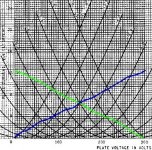
Here's a sketch of a 6SN7 in differential CCS. Pardon my terrible sketch..couldn't figure how to do a plain line in THE GIMP.
Imagine total current always at 6mA. DC plate voltage of 150VDC each. plate voltage of first tube is to scale. plate voltage of second tube (left tube) is inverted on x-axis.
-> input moves the grid voltage of the first tube (right tube) from bias at -4 to -2
-->will change the 2nd tube grid voltage from -4 to -6.
---> plate voltage of right tube will change to ~120vdc.
----> plate voltage of left tube changes to ~180vdc
gain per tube is (150-120)/(-4--2) = -15v/v
total gain is 30v/v, positive or negative depending of how it's referenced
anybody feel free to correct..it's late and i'm tired...
Attachments
On the subject of both tail and plate load CCSs in a diff amp, there is one particular advantage that occurs to me, namely, the ability to draw a substantial current without having to have an insanely high B+. This is useful in the case, for instance, of a 6SN7, which we are told performs best with at least 8mA plate current. Such a high current through a suitable plate load of ~47k would incur a voltage drop of 376v. If the cathodes are at +9v and we need 200v across the tube from plate to cathode, it means we would need B+ to be at least 585v.
Now, with a CCS in each plate load, we can arrange things to work with a much lower B+ using as much current as we like. We need to arrange for the CCS in the tail to run with a little more than twice the current of each plate load CCS. We connect a resistor in parallel with each plate CCS to take the extra current and select its value to give the desired voltage difference between B+ and plate. This voltage difference has to be enough to accommodate the required output voltage swing.
Example: We use a 16mA CCS for the tail and a 7.9mA CCS in each plate. The overall difference in current will be 200uA, or 100uA per plate. So, if we connect a resistor of 470k in parallel with each plate CCS, this will give a B+ to plate voltage drop of 47v. This means we need a B+ of only around 260v and we have 8mA plate current per tube with 200v plate-cathode. The effective load for each plate at audio frequencies will be approximately the same as the resistor (470k), since the CCS that is in parallel with it has a much higher impedance and can be ignored.
I think the above is right but please correct me if I'm wrong.
- Status
- Not open for further replies.
- Home
- Amplifiers
- Tubes / Valves
- Would a Williamson sound better with a CCS tail in the driver?