Hi,
would you please have a look at my hand drawn scetch? I've got the power transformer of an useless, hence scrapped Hammond S6 chord organ. The HV secondary nominally is 285-0-285 Vac. My idea is to use it as the PT of a PP amplifier with 807's. The required screen voltage is 300 Vdc. Can I just connect the input choke to the CT terminal in order to get this voltage without excessive dissipation losses? How do I calculate this choke?
Thanks in advance and a happy new year @All!
Attachments
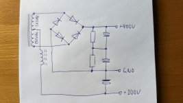
The diode 'bridge' can certainly be use as a full bridge for the 800V rail, and the CT as a full-wave rectifier configuration for 1/2 the 800V. That is a common power supply configuration (especially in Philips PA amps) as the 50% rail is stiff, and it works well with PP output stages where screens need a lower stiff level.
The extra diode in your schematic is redundant for that configuration, but I can see that when the diode is reverse biased then the choke input can swing and should pass current to the 300V feed. For the choke operating with continuous conduction, the bottom diode pair in the bridge will be alternating on all the time, which shouldn't alter the operation of the top diode pair for the 800V rail. I'm a bit unsure about how much interaction occurs when the 400V rail diode is conducting to maintain the 400V rail, given the choke waveform will be modified (from normal) during that time. So seems like a worthwhile trial is needed 👍
The extra diode in your schematic is redundant for that configuration, but I can see that when the diode is reverse biased then the choke input can swing and should pass current to the 300V feed. For the choke operating with continuous conduction, the bottom diode pair in the bridge will be alternating on all the time, which shouldn't alter the operation of the top diode pair for the 800V rail. I'm a bit unsure about how much interaction occurs when the 400V rail diode is conducting to maintain the 400V rail, given the choke waveform will be modified (from normal) during that time. So seems like a worthwhile trial is needed 👍
The centre tap is at the mid-point of the bridge output rails during peaks and will float to some extent between peaks. The choke and diode won't do anything - the capacitor will stiffen it up between peaks, but you might as well just connect it to the mid-point of the caps on the output of the bridge, meaning you can lose the resistors (although they might be useful for safely discharging the caps anyway)
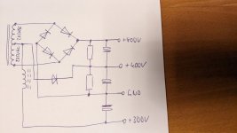
It's not about centering both capacitors in the 800 Vdc supply that I'm common with, it's about the possibility of decoupling a choke input filter to achieve roughly 300 Vdc from a 400 Vdc line fed from the CT.
Best regards!
Best regards!
The CT is already at the mean voltage, ie 400V, you can't low pass filter it to any other value! Have a go simulating it perhaps to convince yourself?
The top or bottom arms are alternately pinned to GND by the bottom two diodes of the bridge throughout each mains half-cycle. The 400V feed is charged when each half winding reaches its peak voltage and forces the single diode to conduct. In between the time of the bridge bottom diodes swapping conduction, the CT voltage rises towards its peak and then falls - as per a normal choke input waveform, with choke current commutated by the two bottom diodes of the bridge.
I agree - those bottom two diodes would be conducting the sum of output rail charging currents (800V, 400V, 300V rails), which would include two overlapping portions around the peak of each mains half-cycles (for 800V and 400V rails), although that operation is typical of many Philips valve PA amp supplies I've come across.
- Home
- Amplifiers
- Power Supplies
- Would a CT work as a choke filter input?