hey everyone,
i could use some "good news" ( crossing fingers) 🙁
i recently measured the idle power consumption of my event opal monitors ( class a/b amps) after suspecting a transformer overheating issue may be happening
line voltage 122v
line current on right channel 0.478A, left channel 0.419A
so, power consumption of 58w and 51w
from the opal spec sheet i understand the idle consumption to be around 20w
so im around 2-3 times higher
may this indicate transformers that have gone bad ? ( been used by the original owner for around 10 years, recording studio,etc..)
and there may be some evidence of long term overheating of the transformers...
a few wires from transformer have become brittle and cracked at the exit point of the transformer
and
after being used for a while, even just on idle, when the amps are turned off and the cast aluminum enclosures opened, there is quite a bit of heat coming from inside, and the surface of the transformers are quite warm to the touch
* acoustically sealed enclosures, no ventilation for the electronics...large heatsink for output devices which never goes beyond warm/ very warm
and, the oem rubber discs under and above the transformers had become brittle/ solid
the opals otherwise seem to work well, the bias voltages are set to around 17mv ( around 56mA) ,etc...
im trying to avoid having to source new transformers, but at the same time i already invested the time and resources to restore these monitors,which are quite nice, since id like to keep these monitors long term
* 115 primary, 15v, 30v, and 30v secondary, 250va, toroid
normal operation or evidence of worn out/ overheated transformers?
cheers
sw
Attachments
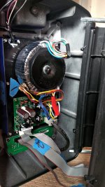
See the brown cylinders left middle of your picture?
They are electrolytic caps, the time fuses of the electronics market.
The marketing people determine how long they want a product to last, then the engineers buy electrolytic caps as cheap as necessary to fail at the proper time. Various grades of sealant is used to keep the water in, from red gum rubber (500 hour service life) to epoxy (50 years anyway, since they were invented in the 70's.)
I'd change the e-caps in a heartbeat, then see if the transformers cool down. This is over 10 years old isn't it? Typical life for PA market gear. Consumer electronics 1 year is often the desired failure date.
A little heat shrink tubing around the cracked insulation might help prevent a short, although moving the wires may make the short inevitable.
I buy 3000 to 10000 hour life e-caps when I replace any, as I don't like doing this job 4 times as I have on my 1961 build 1970 purchase ST70. Farnell & digikey list the service life in the cap selector table (if you ask for it) mouser makes you download each manufacturer's datasheet and read it. Digikey has the best shipping to CA. Farnell often will ship out of the US, using UPS even if you specify mail sometimes, which incurs a $20 customs loan origination fee at the border. Digikey uses a CA office and pays customs themselves. There is also a distributor in Vancouver I don't use, bill's or something?
Wear safety glasses when soldering, solder can splash in the eyes. don't wear jewelry on hands or neck when around electronics. Don't use 2 hands to measure with the power on, 25 v across your heart can stop it. Mark the plus on the board with a sharpie before removal, e-caps put in backwards can explode on power up.
After the main (big) rail e-caps are replaced, the little ones usually go one at a time over the next couple of years. So your system is broken all the time. I change them 2 at a time between function tests to prove I didn't insert a problem solder joint or wrong part. But when 1 goes, I usually do them all. Then the system acts like new for however long you bought the caps for. Pots and rubber parts (speaker surrounds) have their own failure dates. Note bipolar e-caps are frequently used in the crossover if there are 2 drivers, look for those on their own board up in the front someplace. rated "xxx volts NP" for no-polar. Caps have shrunk, these can often be replaced by forever polyprophylene caps in a big speaker cabinet. Any ecaps 10 uf or smaller, I use multilayer ceramic caps instead. Never replace again.Double rated voltage on ceramic caps, they are non-linear and higher voltage straigtens out the curve some. some ceramic caps are microphonic, never done a speaker so don't know how big a problem that is. Not a problem in my H100 organs which can rattle the chandelier on the bass notes.
Last edited:
yes, all caps have been replaced very recently. high temp ucc, panasonic fr and fc, and some mundorf (series signal caps)
In that case check idle current no signal on output transistors. About 10-20 ma is typical on TO3 or TO3p transistor pairs. Take voltage across emitter resistors and divide by resistor value. If 100 ma or more would explain transformer heating.
If that is not out of control, you may be right about the transformers.
If that is not out of control, you may be right about the transformers.
I would disconnect the secondaries on the transformer then measure the current drawn with nothing but the primary connected to the mains. It should be next to nothing unless you have a shorted turn which will cause eddy currents to form and cause heat.
It may dimly light a 15W incandescent lamp in series with it and that would be normal.
It may dimly light a 15W incandescent lamp in series with it and that would be normal.
i tested one transformer, secondaries disconnected, all else the same, and current stabilized after couple of minutes at 0.035A ( so 4.27w, with a 122v line)...?
That's just 35 mA of magnetizing current. No problem there since that's less than the data sheet spec. of many generic toroids rated 225-250VA.
Last edited:
so then what may be the cause behind the excess heat from the transformer, and the much higher than spec power consumption at idle ?
The first problem is assuming that the manufacturers idle consumption is to be trusted. It could very well be erroneous.
Were talking power electronics here though with a combination of lower power supporting circuitry. If any of the supporting circuitry were to develop a fault that would cause the idle consumption to increase from 20 watts to 50 watts the speakers would not be working any more.
Likewise the power amplifier section itself contains a bunch of low power bits surrounded by the heavy lifters - the output transistors. The only thing, in a design like this, that can reliably cope with increased power dissipation are the output transistors.
Most designs like this actually use chip amps so most of the power amplifier stuff all fits inside a single device. Some of these require external biasing components and some don't. Most don't. If this were a normal power amplifier I'd expect the bias setting circuitry to have shifted over time and needs readjusting back into spec. But as these probably use chip amps then there's nothing to adjust.
We need more information. What is the model number of the speakers? Hopefully there are pictures online of the circuit boards etc. Or you can pull these apart more yourself to find out.
If they've always run hot and they've always worked this way then they could just be working as intended.
Another thing to point out is that the current you measured and then calculated from is assuming the speakers have a power factor of one, unless you used a proper power meter that will tell you apparent and real power consumption.
Last edited:
hi, ...as per original post, the model of the monitors is the event opal
discreet components throughout, class a/b, toshiba 2sa1943/5200
all caps have been changed , same for rectifiers, same for output devices, and bias trimpots
bias has been set per oem specs
current was from the ac line in
discreet components throughout, class a/b, toshiba 2sa1943/5200
all caps have been changed , same for rectifiers, same for output devices, and bias trimpots
bias has been set per oem specs
current was from the ac line in
If the bias is in spec and everything else is working fine then there's unlikely to be anything wrong. The only part of the speakers that can realistically dissipate all the extra power Vs the manufacturers listed idle power is the output stage. If you've confirmed that the bias is set correctly then the output stage is doing what it should.
To get a more realistic idea of the idle power it would make more sense to measure the DC current draw on each of the individual DC rails, calculate the power for each and add them together. At least then you'll know which part of the speakers electronics are actually consuming all the power too.
To get a more realistic idea of the idle power it would make more sense to measure the DC current draw on each of the individual DC rails, calculate the power for each and add them together. At least then you'll know which part of the speakers electronics are actually consuming all the power too.
- Home
- Amplifiers
- Solid State
- Worn out TX ?