I have no real grasp of speaker theory, but I see it is said that at low frequency, the cone breakup isn't supposed to do significant damage , yet Seas as well as 10 inch speakers in general are renowned for cone breakup prevention delivering a larger meaningfull frequency response with lower natural efficiency , but being a bit aware of the material physics and this reading this topic :I went for Seas W26FX002. I haven't listened to them yet, but they sure do look nice. When I tap them, they have a low, doof! that is absolutely amazing. I doubt and 15"-18" PA woofer can sound that good and relaxed in the bass. But we will see.
https://www.diyaudio.com/community/threads/cone-breakup.58817/post-661789
I also remembered two things: large area speakers are easily dissipating the cone breakup resonances into harmonic distortions which add to the sound itself making it less precise, but more bodied or perhapse more midranged , while for smaller speakers there's also an old variation of Bose speakers I have to show as its foam placed at the center made me curious some times ago at least as cheap damping technology.I wonder what more bodied voices in speakers theory have to say about that.I remember the most natural base-mid speaker I heard was a 15 inch open baffle speaker driven by 1.5 watts 2A3 tube amp...letting the air around it dissipate all the bad things that might have happended, but I suppose that air and large area paper speakers are just naturally converting all the resonances into meaningful sound.I see tons of theory around making the speakers smaller and that makes me think that making the speakers smaller and more linear while stressing the amp more is all that modern speakers have achieved.Please correct me if I'm wrong!
Attachments

I found your post(s) in this thread unclear and confusing. What function/graph/diagram are you looking for?I am taking some time to peek inside the driver efficiency and implications of that. ..
This graph below is just a starter, work in progress, and will show 1Watt SPL output (kind of efficiency in decibels)of some known drivers, which I will add. ... Compromise is being made by setting the reference box volume and a port.... Looking at ported graphs, it looks like the port doesn't do a thing.
https://ibb.co/DfXXnG3
I wonder why high end driver manufacturers decide to use stiffer suspension, to lose on both sensitivity and efficiency, especially in the upper range of bass.
SPL at 1W input is defined as SPL measured with 1W electrical input signal at the nominal loudspeaker impedance - usually 8 or 4 ohms.
For nominally 8 ohms loudspeakers input voltage is 2.83 V - that is 2.83x2.83/8 = 1 W power.
For nominally 4 ohms loudspeakers input voltage is 2 V - that is 2x2/4 = 1 W power.
I don't know what your graph is representing. Shape of SPL at nominal 1W input is defined by TS parameters of the used woofer and the volume and tuning frequency of the box. If you choose so called maximum flat TS alignments, than the SPL at 1 W graph represents ideal high-pass filter. Your graph doesn't represent this.
Last edited:
Yes, but 2,83V is not a power response. The power with constant voltage differs wildly with frequency not only generally, but also between speaker.Can you expand on that a little? For example, if I run a 2.83V frequency sweep of a driver plus enclosure combination, it produces a certain SPL response.
This would be more details set to be sure, but yes.Of course, as you allude, a 4-ohm driver will draw more power than an 8-ohm driver, speaking in nominal terms. Hence, although the drivers are equally sensitive the one with the higher impedance is more efficient, is it not?
Yes.As we go towards higher frequencies, there will generally be a flattening off in the response (before the cone breakup modes), and the height of that plateau in dB_SPL will be strongly related to the sensitivity of the loudspeaker plus enclosure combination, won't it?
True. The devil is in the meaning of "damped". Damped fortunately also means less power input. Adding decibels of EQ would mean add the proper amount of power, not giving it more than to other speaker with high Qes.For a driver with a highish BL, we usually find that it has a low Qes, leading to a low Qts, and a highly damped natural low-frequency response. Would that be a reasonably accurate observation?
Because of heat.Hence, why would anyone use these values as reference data to make a decision about speaker output capability?
Some enclosures have one or more impedance minimums/valleys where a lot of power is drawn, and even lesser cone excursion happens. That is pretty bad for speaker output.
Not looking, but rather making, and from obtained data, I reach new conclusions. The graph is "one watt of real power" SPL.I found your post(s) in this thread unclear and confusing. What function/graph/diagram are you looking for?
With 1Watt of real power across the band, NO. No nominal impedance. That is sensitivity graph. I do not need that.SPL at 1W input is defined as SPL measured with 1W electrical input signal at the nominal loudspeaker impedance - usually 8 or 4 ohms.
Yeah, speakers are not 8Ohms across the band, are they?For nominally 8 ohms loudspeakers input voltage is 2.83 V - that is 2.83x2.83/8 = 1 W power.
The graph represents frequency response based on 1Watt of input power. True power. Not nominal.I don't know what your graph is representing.
Of course it doesn´t. I am after some advanced stuff.Shape of SPL at nominal 1W input is defined by TS parameters of the used woofer and the volume and tuning frequency of the box. If you choose so called maximum flat TS alignments, than the SPL at 1 W graph represents ideal high-pass filter. Your graph doesn't represent this.
Your answers are even more confusing.
Do we need some new type of an amplifier which delivers constant power irrespective of the loudspeaker varying impedance? Or do we need some new type of loudspeaker with constant, flat impedance across its operating bandwidth? Or both? What will be the price and advantage of those new types of amplifiers and/or loudspeakers over exiting, conventional ones?
Almost all (99.99999%) amplifiers on the market are conventional types with very low output impedance, which results in a flat (more or less) frequency response from any loudspeaker, which is not affected by the varying (by frequency) loudspeaker impedance.
OK, so you are inputing constant 1W of power into a loudspeaker varying (with frequency) impedance. May I ask how this graph will help to provide better/louder sound from the loudspeakers, using conventional amplifiers (with low output impedance)?Not looking, but rather making, and from obtained data, I reach new conclusions. The graph is "one watt of real power" SPL. ... No nominal impedance. That is sensitivity graph. ... The graph represents frequency response based on 1Watt of input power. True power. Not nominal.
Do we need some new type of an amplifier which delivers constant power irrespective of the loudspeaker varying impedance? Or do we need some new type of loudspeaker with constant, flat impedance across its operating bandwidth? Or both? What will be the price and advantage of those new types of amplifiers and/or loudspeakers over exiting, conventional ones?
No, they are not. So?Yeah, speakers are not 8Ohms across the band, are they?
Almost all (99.99999%) amplifiers on the market are conventional types with very low output impedance, which results in a flat (more or less) frequency response from any loudspeaker, which is not affected by the varying (by frequency) loudspeaker impedance.
I can't see any advance here.Of course it doesn´t. I am after some advanced stuff.
Is it the wording, that is confusing, or the approach?Your answers are even more confusing.
As long as the amplifier has enough voltage swing, it indicates, that more efficient speaker will play louder. Because, if it is inefficient, it does not produce sound, but HEAT.OK, so you are inputing constant 1W of power into a loudspeaker varying (with frequency) impedance. May I ask how this graph will help to provide better/louder sound from the loudspeakers, using conventional amplifiers (with low output impedance)?
We do not want heat in the speakers. And if we see that more efficient speaker produces more sound per Watt, it means it produces less heat per Watt. Given the power rating, it then can play louder indeed. The conventional response graph goes agains this, and that is a big problem/mistake.
No, not really. We need capable amp that can provide great voltage and current swings, and can recuperate the inductive energy.Do we need some new type of an amplifier which delivers constant power irrespective of the loudspeaker varying impedance?
There are ideals, and there is reality. This approach would be easiest, but not really doable yet I think. It is good enough if the motor has great magnetic force (Bl * Bl)/Re.Or do we need some new type of loudspeaker with constant, flat impedance across its operating bandwidth? Or both?
Great output capabilities with sustainable power input - lack of overheating, more SPL, and doable grid load. Not everybody can pull 10+KW from the grid everywhere.What will be the price and advantage of those new types of amplifiers and/or loudspeakers over exiting, conventional ones?
Unfortunately, with strong motor speakers, we see it is less. Less enough for people to conclude that the speaker is not suited for bass application. And as this is not sustainable approach, modifications need to be made to the model.No, they are not. So?
Almost all (99.99999%) amplifiers on the market are conventional types with very low output impedance, which results in a flat (more or less) frequency response from any loudspeaker
Oh, it absolutely is! The stronger motor force speakers above all else, have different (heightened) impedance compared to low Bl speakers. And so with higher impedance curves, there is less power going into the speaker. And that of course is misleading to unfair with conventional assesment.which is not affected by the varying (by frequency) loudspeaker impedance.
That can happen. I was looking for people that can. Or at least for objective, particular, concrete, pointed or mathematical denial. It´s just learning, man. That´s what I´m here for.I can't see any advance here.
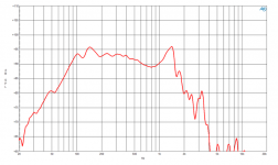
18DS115 frequency response plot looks like it is a bad mid woofer 😀
https://www.bcspeakers.com/en/products/lf-driver/18-0/8/18ds115-8
But it takes lots of power and the graph turns into anything with EQ. So, this makes less heat more sound when lots of power is applied and today with cheap power and DSP this is the way to go, more sound per currency unit taking less space as well.
I guess this is very relevant with Pro audio world, but does it extend to home audio? I guess your mission could potentially extend it more to home audio if people were aware the frequency response plot does not tell the whole story. Do we ever need such high SPL in livingroom? Can you expand how all this relates or could relate to home audio, the hifi folk?
Attachments
I think a lot comes down to MMD. A large surface woofer likea 15"-18" can't be light and rigid enough to not have unwanted distortion.
If the energy was more evenly distributed with a larger diameter voice coil, it might help, but a smaller diameter VC 15" woofers can sound good too, and often have cleaner midrange, like old vintage 15" drivers. But maybe not so precise bass.
Maybe if you study the breakup in slow motion with lasers, or something, you can come up with a 15" woofer that has less unwanted distortion, like Celestion tried to do with the low midrange compression driver Celestion AXi2050.
But I think a good bet is to use a smaller surface woofer, like a 10"-12", that is low sensitivity and ported to go low, but also play up to 500-1000Hz and still sound good for picky people.
When it comes to midbass horns, I think the demands for a clean sounding woofer is even more important. Again, most 15" are ruled out.
It certainly LOOKS like it. Or it alludes you to see it that way. In the meantine, that thing outputs a lot of bass.18DS115 frequency response plot looks like it is a bad mid woofer 😀
https://www.bcspeakers.com/en/products/lf-driver/18-0/8/18ds115-8
It takes less power. The speaker takes less power to begin with. So EQing up means you just push proper power into the speaker.But it takes lots of power and the graph turns into anything with EQ.
Cinema is made with PA speakers also, normally, people now go ham on SPL. And so PA at home is now seen quite often.So, this makes less heat more sound when lots of power is applied and today with cheap power and DSP this is the way to go, more sound per currency unit taking less space as well.
I guess this is very relevant with Pro audio world, but does it extend to home audio? I guess your mission could potentially extend it more to home audio if people were aware the frequency response plot does not tell the whole story. Do we ever need such high SPL in livingroom? Can you expand how all this relates or could relate to home audio, the hifi folk?
PA woofers needs to be cranked up to come alive. Listening to whispering levels in the livingroom using PA woofers is a bit overkill.
Good PA woofers have nearly unmeasurable levels of distortion and compression at domestic listening levels.
That is partially a myth, PA drivers sound fine (at least those I've had) with low level no problem. Only thing that remains is that they have enough SPL capability, one Can crank up as much as one likes until it is not fun anymore but still sounds fine, it is just too loud for the hearing system. Maximal fun can be reached 😀 One downside that might trouble is amplifier noise, need to have good low noise amplifier for high sensitivity system. With low noise amp it is possible to enjoy whisper level listening at night and loud level when it is time to awe.PA woofers needs to be cranked up to come alive. Listening to whispering levels in the livingroom using PA woofers is a bit overkill.
I'll agree these particular modern drivers Crashpc mentioned would be overkill with their capability at home but so would many others. It looks to me that any driver plays fine at low level and problems start when more power is applied. The modern drivers take it even further, more SPL capability, even though the traditional frequency response plot doesn't give the impression before checking the details.
Here Chris661 posted some measurements of a driver playing with various level. It is not a PA driver though. Frequency response stays the same from in-audibility up
https://www.diyaudio.com/community/...-driver-output-capability.357209/post-6277664
Last edited:
My thinking is that if Mmd is 200 gram, like on a 15 inch PA bass woofer, instead of 35 gram, like on a 10 inch Seas woofer, then you need more power to get to the sweet spot for the heavier cone.
It may be argued that sims do not dictate choices, but there sure appears to be the consequence that a sub-woofer response that looks flat is the one to pursue. Yet, as you mention a few times in your illuminating posts, nothing is easier to re-tune today (using DSP, etc) than frequency response....As explained before, I am attempting to show, that we do not reach our extreme goals through flat frequency response based on voltage input.....
Actually, pretty silly to aim for a flat sub FR. Never finished tuning any system mine that didn't have a big whack of boost as the bass freq goes lower. A good reason to avoid small boxes because that makes it hard to crank out bass below the box's unaided limits.
My experience is that installing the box in your music room makes all the difference - and moving the box around in your room changes FR once again quite a bit.
B.
You would need more motor force, but a stronger magnet can do that. I ran domestic speakers with PA drivers for a long time using a 1 watt class A amplifier, and that sounded great. According to Pano’s voltage test, I had too much amplifier power and only needed about 1/4 watt for the loudest I ever used itMy thinking is that if Mmd is 200 gram, like on a 15 inch PA bass woofer, instead of 35 gram, like on a 10 inch Seas woofer, then you need more power to get to the sweet spot for the heavier cone.
Brian
Yeah, but even if it is loud to you in your livingroom, it may not be very loud for the PA driver. It was probably designed to operate at around 50-100W. At such levels, to be rigid is more important than being light weight and produce fine details in bass even at low levels.
For true subwoofer work, the cone assembly weight does not affect the output in a linear fashion. It is less problematic. If we are to compare weight though, we need to compare motor strength hand in hand with it. What is the Re and Bl of that Seas woofer?My thinking is that if Mmd is 200 gram, like on a 15 inch PA bass woofer, instead of 35 gram, like on a 10 inch Seas woofer, then you need more power to get to the sweet spot for the heavier cone.
Both.Is it the wording, that is confusing, or the approach?
You just described class-D amplifier as the preferred amplifier suitable for your idea for higher efficiency woofers. So we are talking about bog-standard amplifier with low output impedance, connected to a (electrodynamic) loudspeaker. Good!As long as the amplifier has enough voltage swing, it indicates, that more efficient speaker will play louder. Because, if it is inefficient, it does not produce sound, but HEAT.
We do not want heat in the speakers. And if we see that more efficient speaker produces more sound per Watt, it means it produces less heat per Watt. Given the power rating, it then can play louder indeed. The conventional response graph goes agains this, and that is a big problem/mistake.
...
No, not really. We need capable amp that can provide great voltage and current swings, and can recuperate the inductive energy.
Now we can safely turn to analyze loudspeakers only (whether they can be made to be more efficient), because the amplifier type is already fixed.
Implication of this is: your “green” quest for “more sound (i.e. SPL) per Watt, less heat per Watt” is dictated by the loudspeaker impedance only! Especially the second part – “less heat per Watt” (efficiency – that is). Loudspeaker impedance vs frequency function is dictated by the woofer TS parameters and the type of the loudspeaker enclosure. If we analyze loudspeaker impedance vs frequency, we can see that:
1. For sealed box: woofer impedance has only one peak at the so called Fc – resonant frequency of woofer in a sealed box (which is always higher than Fs – resonant frequency of the same woofer in free air). Impedance peak around box resonant frequency Fc is the only part of the woofer operating bandwidth where high efficiency (less heat per Watt) is possible. Designing woofer with suitable TS parameters to exhibit high impedance peak over larger frequency band is the (only) way to do. And it was done in 2005, see the AES paper here:
https://www.aes.org/e-lib/online/browse.cfm?elib=13413
https://www.aes.org/images/e-lib/thumbnails/1/3/13413_full.png
Unfortunately, available bandwidth (with the high impedance/efficiency) is rather narrow. There are no commercial subwoofers exploiting this design – surely because of the aforementioned deficiency.
2. For vented (bass-reflex) box: woofer impedance has two peaks – one below and one above the tuning frequency. In this context, only the impedance above tuning frequency response is available for use. Unfortunately, this peak is very narrow, so the available bandwidth with high efficiency is very narrow and practically unusable.
Good! Dipole electrodynamic planar types of loudspeakers (e.g. Magnepan) has constant impedance, but they are not good candidates for subwoofers, anyway. So, we can freely eliminate all dipole planar “woofers” in our analysis. What is left is conventional moving coil (or moving magnet) electrodynamic woofer.There are ideals, and there is reality. This approach would be easiest, but not really doable yet I think. It is good enough if the motor has great magnetic force (Bl * Bl)/Re.
I didn’t understand an iota of this.Unfortunately, with strong motor speakers, we see it is less. Less enough for people to conclude that the speaker is not suited for bass application. And as this is not sustainable approach, modifications need to be made to the model.
On the contrary, absolutely it isn’t! Amplifier with low output impedance is almost perfect voltage source, so it is not affected by the varying loudspeaker impedance at all! In spite of the varying impedance, amplifier+loudspeaker will deliver flat frequency response – that is constant SPL for constant voltage output from the amplifier (which can’t operate in a different way)!Oh, it absolutely is! The stronger motor force speakers above all else, have different (heightened) impedance compared to low Bl speakers. And so with higher impedance curves, there is less power going into the speaker. And that of course is misleading to unfair with conventional assesment.
Higher impedance of the loudspeaker at some frequency (the resonant frequency of woofer in a box, for example) indeed means “less power going into the speaker” (for the same SPL) - but that is the definition of bigger efficiency! That is your goal, isn’t it? You are losing the sight on the most important (to you) thing – bigger efficiency!
It already happened in 2005 (abovementioned AES paper). Yes, it can be done, and it was done. But no joy, it is almost unusable.That can happen. I was looking for people that can. Or at least for objective, particular, concrete, pointed or mathematical denial. It´s just learning, man. That´s what I´m here for.
For true subwoofer work, the cone assembly weight does not affect the output in a linear fashion. It is less problematic. If we are to compare weight though, we need to compare motor strength hand in hand with it. What is the Re and Bl of that Seas woofer?
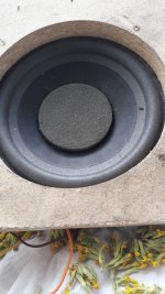
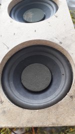
Seas W26FX002, 10” paper cone
I also have the smaller magnet Seas A26. Here are both in WinISD in my cabinet:

I need to finish the grilles, and then I can measure real world frequency response! 🙂 Looking at the simulation I am fairly certain it will sound like something.
I have a 40 W Musical Fidelity Electra E10 or two XTZ 500W plate amp with analog input and digital dsp. Too many ADC DAC conversions on the XTZ amps but clean and endlessly powerful bass. Can’t decide which to start with. The Electra needs new PSU caps.
Only got the red horn hooked up:
Last edited:
Indeed, but given the topic, we can kind of ignore that. At the moment, I am not looking at system efficiency yet. Just the speaker.You just described class-D amplifier as the preferred amplifier suitable for your idea for higher efficiency woofers. So we are talking about bog-standard amplifier with low output impedance, connected to a (electrodynamic) loudspeaker. Good!
It is rather power density quest. We can get more SPL from smaller bins. That´s the game. Don´t give them ideas, or they will ban speakers over 500W soon...Now we can safely turn to analyze loudspeakers only (whether they can be made to be more efficient), because the amplifier type is already fixed.
Implication of this is: your “green” quest
Half way, or rather not. This might be the point on which we need to expand, Impedance does not account for whole SPL output. Impedance does not create decibels. It only does power draw. The transformation to sound is another thing. But if we set all else to equals, then yes, with very important details to that. Impedance has spectrum, shape and phase. These are major parts of the problematics we need to take into account, and in the moment, we do not do that.for “more sound (i.e. SPL) per Watt, less heat per Watt” is dictated by the loudspeaker impedance only!
The efficiency of the speaker, and heat loss, needs to be assessed also far from the peak. The peak has some shape, coming from peak to base. With high motor force drivers, the base of the impedance curve is much more broad, and is more affected by phase relations between current and voltage. Current flows where voltage is not present, and vice versa.Especially the second part – “less heat per Watt” (efficiency – that is). Loudspeaker impedance vs frequency function is dictated by the woofer TS parameters and the type of the loudspeaker enclosure. If we analyze loudspeaker impedance vs frequency, we can see that:
1. For sealed box: woofer impedance has only one peak at the so called Fc – resonant frequency of woofer in a sealed box (which is always higher than Fs – resonant frequency of the same woofer in free air). Impedance peak around box resonant frequency Fc is the only part of the woofer operating bandwidth where high efficiency (less heat per Watt) is possible.
I think there are. It is just a part incorporated in the design, not the whole matter. Powersoft IPAL solution revolves around that quite a lot.Designing woofer with suitable TS parameters to exhibit high impedance peak over larger frequency band is the (only) way to do. And it was done in 2005, see the AES paper here:
https://www.aes.org/e-lib/online/browse.cfm?elib=13413
https://www.aes.org/images/e-lib/thumbnails/1/3/13413_full.png
Unfortunately, available bandwidth (with the high impedance/efficiency) is rather narrow. There are no commercial subwoofers exploiting this design – surely because of the aforementioned deficiency.
The whole band is usable. Even in the impedance valley, efficiency still can be assessed, and is of course related to speaker motor strength. It is no win over there, I try to partially avoid it, but it is still important chunk of the problem. I plotted the efficiency graph with wented box already. You can see that the vent does not have much effect on efficiency, as we do not see any peak or walley in efficiency in the graph. It does very different thing, to efficiency, than it alludes.2. For vented (bass-reflex) box: woofer impedance has two peaks – one below and one above the tuning frequency. In this context, only the impedance above tuning frequency response is available for use. Unfortunately, this peak is very narrow, so the available bandwidth with high efficiency is very narrow and practically unusable.
Yup. Still it must be obvious to you, that it will yield different outcome if you want to extract movement/sound from small piece of wire, or a lot of wire in strong magnetic field.Good! Dipole electrodynamic planar types of loudspeakers (e.g. Magnepan) has constant impedance, but they are not good candidates for subwoofers, anyway. So, we can freely eliminate all dipole planar “woofers” in our analysis. What is left is conventional moving coil (or moving magnet) electrodynamic woofer.
This is so basic stuff. We absolutely do not need anything more than common sense with most most basic physics. Less magnetic field and less wire, less force. That easy.
How the hell is this not obvious.
Low Qes high motor force driver appears to provide low SPL in bass region. That is only true if we feed it with constant voltage. But there is no need for that anymore. We can ignore that approach, we can feed proper voltage to it, and exploit the driver to give us much more.I didn’t understand an iota of this.
This does not make sense with offtopic amplifier issues again. Of course it is not affected, but it was not a point and I see no connection. What I say is that higher speaker impedance will cause less SPL given the constant voltage.On the contrary, absolutely it isn’t! Amplifier with low output impedance is almost perfect voltage source, so it is not affected by the varying loudspeaker impedance at all!
Not anymore.In spite of the varying impedance, amplifier+loudspeaker will deliver flat frequency response – that is constant SPL for constant voltage output from the amplifier (which can’t operate in a different way)!
It is off the impedance peak too. I am losing the understanding too. We should start with the basics.Higher impedance of the loudspeaker at some frequency (the resonant frequency of woofer in a box, for example) indeed means “less power going into the speaker” (for the same SPL) - but that is the definition of bigger efficiency! That is your goal, isn’t it? You are losing the sight on the most important (to you) thing – bigger efficiency!
I use it very successfully, Powersoft and other manufacturers use it too.It already happened in 2005 (abovementioned AES paper). Yes, it can be done, and it was done. But no joy, it is almost unusable.
Back to basics. A coil, attached to cone. The more coil pushes, the further the cone goes, the more SPL it creates. High motor force drivers will push more Newtons per Watt. How is it possible to deny this?
- Home
- Loudspeakers
- Subwoofers
- Woofer efficiency revisited