Hello,
I would like to show the design philosophy and practical implementation of a phase-accurate WMTMW Baekgaard loudspeaker here.
The Baekgaard loudspeaker dates back from the seventies with Erik Baekgaad working for Bang&Olufsen. The AES publication is here, dating back from March 1975 : http://www.aes.org/tmpFiles/elib/20100925/2480.pdf
The Beovox M70 is one B&O commercial implementation in 1975 : Beovox M70 Passive Loudspeakers
The Beovox S45 is one B&O commercial implementation in 1976 : Beovox S45 Passive Loudspeakers
The Beovox S45-2 is one B&O commercial implementation in 1978 : Beovox S45-2 Passive Loudspeakers
The S45 should be a WMTMM loudspeaker but unfortunately it went WMT for cost reasons, maybe.
The M70 is a S45 with a specialized deep-bass driver, hence bigW-WMT.
I own 2 pairs of S45 and one pair of M70 in original state.
The S45 sounds terrible (bad) by nowadays standard, agressive high range and non-existing deep bass. They were quoted as "bright" when launched.
The MT70 sounds better with a smooth medium and high range. The M70 has SEAS dome tweeters instead of Philips dome tweeters in the S45. The M70 deep bass is decent.
The Beovox S45 should not be confused with the Beovox S22, S25, S30, S35 and S40. Those two are conventional 2-way designs.
S30 in 1975 : Beovox S30 Passive Loudspeakers
S22 in 1977 : Beovox S22 Passive Loudspeakers
S25 in 1977 : Beovox S25 Passive Loudspeakers
S35 in 1977 : Beovox S35 Passive Loudspeakers
S40 in 1980 : Beovox S40 Passive Loudspeakers
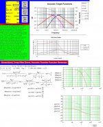
The Baekgaard is an elegant crossover approach based on reassuring & straightforward maths. Let us consider three 2nd order system. Let us say they share the same denominator in their transfer function. Their denominator = s**2 + (Q**-1)*s + 1.
The s variable tracks the relative frequency in complex notation. When s = 1, you are at the central frequency of the filter.
Q = 0.707 for a Butterworth shape factor (restricted bandpass bandwith).
Q = 0.500 for a Bessel shape factor (regular bandpass bandwith)
Q = 0.333 for a very soft shape (extended bandpass bandwith)
Those are fine values for Q in a Baekgaard approach.
Now, look how everything simplifies down if :
- the Baekgaard highpass has the Numerator = s**2
- the Baekgaard bandpass has the Numerator = (Q**-1)*s
- the Baekgaard low pass has the Numerator = 1
What's happening when you sum the three ouputs ?
You get the numerator equal to s**2 + (Q**-1)*s + 1.
Knowing the denominator is s**2 + (Q**-1)*s + 1.
This means a perfect unity transfer function.
This is the beauty of the Baekgaard.
Amplitude gets thus perfectly reconstructed.
Phase gets thus perfectly reconstructed.
The group delay of the reconstructed signal is thus constant across the entire frequency range.
But wait a minute, what is the difference between this and a conventional 2-way 2nd order crossover ?
- in the Baekgaard, you get the medium driver as "filler" unit or "missing link" between the woofer and the tweeter
- the medium unit is an absolute necessity because at the crossover frequency, the woofer and the tweeter have the same amplitude (-3dB or -6dB depending on Butterworth or Bessel) but relative 180 degree phase shift. They cancel themselves. At the exact crossover frequency (s=1), the acoustic output is thus only coming from the medium unit. If the medium unit was not there, there would be a huge amplitude dip at the crossover frequency.
- in a conventional 2-way 2nd order crossover, one usually puts the tweeter in reverse phase. This way there is no more dip. In a conventional 2-way 2nd order crossover, if you use Q=0.707 (Butterworth) and if you put the tweeter in reverse phase, you get a +3dB boost instead. If you double the filtering like cascading two Q=0.707 (Butterworth), you get the well known 4th-order Linkwitz-Riley arrangement and perfect amplitude flatness. But, of course, an ugly phase distorsion with 360 degree phase error between low frequency and high frequency.
In a nutshell, the Baekgaard is the native implementation of a 2nd-order frequency splitter. Being 2nd-order, it is natively 3-way, as the math above do explain.
No need to say, I very much like this crossover approach.
Let us now proceed step by step for a year 2010 implementation :
a) We shall implement a Baekgaard crossover at 1700 Hz with Q=0,5. This is a phase accurate crossover (perfect reconstructed phase), however not very selective (2nd order only - quality drivers are thus mandatory), however delivering substantial inter-driver phase shifts in the overlap region (a very compact WMTMW arrangement is thus mandatory).
b) The Baekgaard crossover is easy to implement both in active form and in passive form. You may thus mount your passive crossover in an external box for ensuring compatibility with an active crossover approach.
c) As we need a bass-reflex W section having a -3dB natural bandwith of 35 Hz to 3400 Hz, our W drivers shall not exceed 16 cm in diameter.
d) In a domestic listening environment, two 16 cm diameter W drivers can deliver enough acoustic pressure, provided they have a decent excursion like 4 mm.
e) As we need a medium M section having a -3dB natural bandwith of 425 Hz to 6800 Hz, our M drivers can be 8 cm or 10 cm in diameter with low excursion and low power handling.
f) As we need a tweeter section having a -3dB natural bandwith of 850 Hz to 15 kHz, a high quality 1 inch dome tweeter with built-in rear chamber would be the best choice, with decent power handling.
g) Later on, for increasing the maximum sound pressure level at 35Hz, we can build two or four W---W columns, same height as the main WMTMW colums, assisting them in the deep bass range. The crossover between the W---W column and WMTMW column shall be active, avoiding expensive big coils and unreliable big caps. The subwoofer filter may thus be 1st order at 120 Hz. The 1st order is chosen in order to keep the relative phase shift below 90 degree. One may opt for a Lipshitz-Vanderkooy phase-compensated 2nd order Bessel crossover for the subwoofer, providing a zero relative phase shift, but causing a 180 degree reconstructed phase shift error in the 60 Hz to 240 Hz range. One may opt for a digital Lipshitz-Vanderkooy delay-compensated 4th order Bessel crossover for the subwoofer, providing a virtually zero relative phase shift, and causing no reconstructed phase shift error in the 60 Hz to 240 Hz range. With this active crossover approach for the subwoofer option, we can use a few inexpensive power amps in the 35 Hz to 120 Hz range.
Let me know if you feel interest for such WMTMW Baekgaard arrangement. If yes, let us select the drivers, running some simulations.
Regards,
Steph
I would like to show the design philosophy and practical implementation of a phase-accurate WMTMW Baekgaard loudspeaker here.
The Baekgaard loudspeaker dates back from the seventies with Erik Baekgaad working for Bang&Olufsen. The AES publication is here, dating back from March 1975 : http://www.aes.org/tmpFiles/elib/20100925/2480.pdf
The Beovox M70 is one B&O commercial implementation in 1975 : Beovox M70 Passive Loudspeakers
The Beovox S45 is one B&O commercial implementation in 1976 : Beovox S45 Passive Loudspeakers
The Beovox S45-2 is one B&O commercial implementation in 1978 : Beovox S45-2 Passive Loudspeakers
The S45 should be a WMTMM loudspeaker but unfortunately it went WMT for cost reasons, maybe.
The M70 is a S45 with a specialized deep-bass driver, hence bigW-WMT.
I own 2 pairs of S45 and one pair of M70 in original state.
The S45 sounds terrible (bad) by nowadays standard, agressive high range and non-existing deep bass. They were quoted as "bright" when launched.
The MT70 sounds better with a smooth medium and high range. The M70 has SEAS dome tweeters instead of Philips dome tweeters in the S45. The M70 deep bass is decent.
The Beovox S45 should not be confused with the Beovox S22, S25, S30, S35 and S40. Those two are conventional 2-way designs.
S30 in 1975 : Beovox S30 Passive Loudspeakers
S22 in 1977 : Beovox S22 Passive Loudspeakers
S25 in 1977 : Beovox S25 Passive Loudspeakers
S35 in 1977 : Beovox S35 Passive Loudspeakers
S40 in 1980 : Beovox S40 Passive Loudspeakers
The Baekgaard is an elegant crossover approach based on reassuring & straightforward maths. Let us consider three 2nd order system. Let us say they share the same denominator in their transfer function. Their denominator = s**2 + (Q**-1)*s + 1.
The s variable tracks the relative frequency in complex notation. When s = 1, you are at the central frequency of the filter.
Q = 0.707 for a Butterworth shape factor (restricted bandpass bandwith).
Q = 0.500 for a Bessel shape factor (regular bandpass bandwith)
Q = 0.333 for a very soft shape (extended bandpass bandwith)
Those are fine values for Q in a Baekgaard approach.
Now, look how everything simplifies down if :
- the Baekgaard highpass has the Numerator = s**2
- the Baekgaard bandpass has the Numerator = (Q**-1)*s
- the Baekgaard low pass has the Numerator = 1
What's happening when you sum the three ouputs ?
You get the numerator equal to s**2 + (Q**-1)*s + 1.
Knowing the denominator is s**2 + (Q**-1)*s + 1.
This means a perfect unity transfer function.
This is the beauty of the Baekgaard.
Amplitude gets thus perfectly reconstructed.
Phase gets thus perfectly reconstructed.
The group delay of the reconstructed signal is thus constant across the entire frequency range.
But wait a minute, what is the difference between this and a conventional 2-way 2nd order crossover ?
- in the Baekgaard, you get the medium driver as "filler" unit or "missing link" between the woofer and the tweeter
- the medium unit is an absolute necessity because at the crossover frequency, the woofer and the tweeter have the same amplitude (-3dB or -6dB depending on Butterworth or Bessel) but relative 180 degree phase shift. They cancel themselves. At the exact crossover frequency (s=1), the acoustic output is thus only coming from the medium unit. If the medium unit was not there, there would be a huge amplitude dip at the crossover frequency.
- in a conventional 2-way 2nd order crossover, one usually puts the tweeter in reverse phase. This way there is no more dip. In a conventional 2-way 2nd order crossover, if you use Q=0.707 (Butterworth) and if you put the tweeter in reverse phase, you get a +3dB boost instead. If you double the filtering like cascading two Q=0.707 (Butterworth), you get the well known 4th-order Linkwitz-Riley arrangement and perfect amplitude flatness. But, of course, an ugly phase distorsion with 360 degree phase error between low frequency and high frequency.
In a nutshell, the Baekgaard is the native implementation of a 2nd-order frequency splitter. Being 2nd-order, it is natively 3-way, as the math above do explain.
No need to say, I very much like this crossover approach.
Let us now proceed step by step for a year 2010 implementation :
a) We shall implement a Baekgaard crossover at 1700 Hz with Q=0,5. This is a phase accurate crossover (perfect reconstructed phase), however not very selective (2nd order only - quality drivers are thus mandatory), however delivering substantial inter-driver phase shifts in the overlap region (a very compact WMTMW arrangement is thus mandatory).
b) The Baekgaard crossover is easy to implement both in active form and in passive form. You may thus mount your passive crossover in an external box for ensuring compatibility with an active crossover approach.
c) As we need a bass-reflex W section having a -3dB natural bandwith of 35 Hz to 3400 Hz, our W drivers shall not exceed 16 cm in diameter.
d) In a domestic listening environment, two 16 cm diameter W drivers can deliver enough acoustic pressure, provided they have a decent excursion like 4 mm.
e) As we need a medium M section having a -3dB natural bandwith of 425 Hz to 6800 Hz, our M drivers can be 8 cm or 10 cm in diameter with low excursion and low power handling.
f) As we need a tweeter section having a -3dB natural bandwith of 850 Hz to 15 kHz, a high quality 1 inch dome tweeter with built-in rear chamber would be the best choice, with decent power handling.
g) Later on, for increasing the maximum sound pressure level at 35Hz, we can build two or four W---W columns, same height as the main WMTMW colums, assisting them in the deep bass range. The crossover between the W---W column and WMTMW column shall be active, avoiding expensive big coils and unreliable big caps. The subwoofer filter may thus be 1st order at 120 Hz. The 1st order is chosen in order to keep the relative phase shift below 90 degree. One may opt for a Lipshitz-Vanderkooy phase-compensated 2nd order Bessel crossover for the subwoofer, providing a zero relative phase shift, but causing a 180 degree reconstructed phase shift error in the 60 Hz to 240 Hz range. One may opt for a digital Lipshitz-Vanderkooy delay-compensated 4th order Bessel crossover for the subwoofer, providing a virtually zero relative phase shift, and causing no reconstructed phase shift error in the 60 Hz to 240 Hz range. With this active crossover approach for the subwoofer option, we can use a few inexpensive power amps in the 35 Hz to 120 Hz range.
Let me know if you feel interest for such WMTMW Baekgaard arrangement. If yes, let us select the drivers, running some simulations.
Regards,
Steph
Last edited:
Hi Steph,My 2-cent opinions not necessarily yours😀
I've been using 3-way second order LR2 acoustic TP filters as my preferred standard for about 30 years, passive mostly for all my designs(hundreds).
All filter sections + drivers uses a resulting Q = 0.5 where the BP filter have an acoustically first order slope on both sides of the center frequency.
Note: This BP filter is not specific a Bessel-type as a BW type too shares the order too.
At that time I tried Baekgaard (IMO flawed) even/odd order BW filters too and found these only to be motivated when a single speaker is used as a centrally placed real source(IDT=0), thus never allowed to produce phantoms. Note: Surprisingly Baekgaard did never mention a filler driver system comprising of LR2 filter with Q = 0.5 for all driver sections..
I've also tested (W) M-T-M's ((W)) in general but drawing the conclusion that this type is only IMO motivated when the speaker absolute vertical M-T-M's size baffle dimension is at max ~ 20 cm (and only motivated for large listening distances(-venues)).
Thus never larger height dimensions, this to avoid unnecessary uneven magnification of the vertical MAA in comparison to what is normally is achieved when comparing with the proportional horizontal MAA. IME you have to move the T driver – 3dB below ~850 Hz and the BP centered at ~550Hz to avoid the mentioned effect.
When comparing to a normal vertical centrally placed Mono M-T layout., I had to move more than 5.5 m from the source until I judged the localization appearance(inclusive the unavoidable image smear) were about equal.
IME, if placed for stereo listening for distances up to 5m this type have serious flawed localization wise :image smear attributes above the at the normal ear height placed T-driver. When trying to forming central phantoms I always expect the verticals/horizontals to be proportionality centrally located at a straight line between the speakers and as sharp as there would only be a single 2-4” FR driver in a small box.
Filler drivers
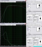
Quick cut and paste of the filter type I,m using:See the picture.
b🙂
I've been using 3-way second order LR2 acoustic TP filters as my preferred standard for about 30 years, passive mostly for all my designs(hundreds).
All filter sections + drivers uses a resulting Q = 0.5 where the BP filter have an acoustically first order slope on both sides of the center frequency.
Note: This BP filter is not specific a Bessel-type as a BW type too shares the order too.
At that time I tried Baekgaard (IMO flawed) even/odd order BW filters too and found these only to be motivated when a single speaker is used as a centrally placed real source(IDT=0), thus never allowed to produce phantoms. Note: Surprisingly Baekgaard did never mention a filler driver system comprising of LR2 filter with Q = 0.5 for all driver sections..
I've also tested (W) M-T-M's ((W)) in general but drawing the conclusion that this type is only IMO motivated when the speaker absolute vertical M-T-M's size baffle dimension is at max ~ 20 cm (and only motivated for large listening distances(-venues)).
Thus never larger height dimensions, this to avoid unnecessary uneven magnification of the vertical MAA in comparison to what is normally is achieved when comparing with the proportional horizontal MAA. IME you have to move the T driver – 3dB below ~850 Hz and the BP centered at ~550Hz to avoid the mentioned effect.
When comparing to a normal vertical centrally placed Mono M-T layout., I had to move more than 5.5 m from the source until I judged the localization appearance(inclusive the unavoidable image smear) were about equal.
IME, if placed for stereo listening for distances up to 5m this type have serious flawed localization wise :image smear attributes above the at the normal ear height placed T-driver. When trying to forming central phantoms I always expect the verticals/horizontals to be proportionality centrally located at a straight line between the speakers and as sharp as there would only be a single 2-4” FR driver in a small box.
Filler drivers
Quick cut and paste of the filter type I,m using:See the picture.
b🙂
Attachments
hi bjorno,
I agree with you. A very compact (W)MTM(W) arrangement is mandatory. Also, all loudspeakers need to be time aligned. The arrangement would thus be, for maximal compacity :
W
MTM
W
Driver selection with 130 mm diameter woofers :
Possible woofers :
Monacor SPH-135 S (bass-reflex 10 liter each, 38 Hz)
Monacor SPH-130 (bass-reflex 12 liter each, 36 Hz)
Monacor SPH-135 C (bass-reflex 14 liter each, 32 Hz)
Possible medium (two of them horizontally) :
any 1 inch like Tang-Band W1-1070 SE
Possible tweeter (one between the two medium) :
any 1 inch like Tang-Band W1-1070 SE (same model as medium)
With this selection, the inter-distances remain very short.
But the power handling of the medium and the tweeter is very small.
This is thus for quiet domestic listening levels.
Driver selection with 175 mm diameter woofers :
Possible woofers :
Monacor SPH-165 C (bass-reflex 15 liter each, 29 Hz)
Monacor SPH-165 CP (bass-reflex 18 liter each, 30 Hz)
Monacor SPH-165 KEP (bass-reflex 18 liter each, 30 Hz)
Possible medium (two of them horizontally) :
any 2 inch like Tang-Band W2-800
any 2 inch like Omnes BB 2.01
Monacor SP6/4
Monacor SP6/4SQ
Monacor SP6/8SQ
Possible tweeter (one between the two medium) :
any 2 inch like Tang-Band W2-803 SM
any 2 inch like Omnes BB 2.01
With this selection, the inter-distances remain short.
The power handling of the medium and the tweeter is small.
This is for moderate domestic listening levels.
Driver selection with 200 mm diameter woofers :
Possible woofers :
Monacor SPH-210 (bass-reflex 21 liter each, 36 Hz)
Monacor SPH-225 (bass-reflex 26 liter each, 33 Hz)
Monacor SPH-200 KE (bass-reflex 40 liter each, 23 Hz)
Monacor SPK-204 (bass-reflex 39 liter each, 23 Hz)
Possible medium (two of them horizontally) :
Monacor SP-7/4
Monacor SP-7/4SQ
Possible tweeter (one between the two medium) :
any 66mm Tang-Band with rear chamber like 25-1414 or 25-1719
any 66mm Omnes with rear chamber like T25 Ti
any 66mm Monacor tweeter with rear chamber, able to handle 850 Hz
With this selection, the inter-distances may cause trouble in the woofer department. They need to be matched.
The power handling of the medium and the tweeter do improve.
This is for normal domestic listening levels.
Driver selection with 250 mm diameter woofers :
Possible woofers :
Monacor Raptor-10 (bass-reflex 20 liter each, 29 Hz)
Monacor Sonic-10 (bass-reflex 34 liter each, 20 Hz)
Monacor SPH-275 C (bass-reflex 40 liter each, 33 Hz)
Monacor SPH-255 (bass-reflex 53 liter each, 28 Hz)
Possible medium (two of them horizontally) :
any 3 inch Tang-Band like W3-316B or W3-871
any 3 inch Omnes 3 like BB 3.01
Monacor SPH 30X/8
Monacor SPH 30X/4
Monacor SPH 75/8
Monacor SPH 75/4
Monacor SP-45/8
Monacor SP-45/4
Monacor SP-30
Monacor SP626/8
Monacor SP-8/4
Monacor SP-8/4SQ
Possible tweeter (one between the two medium) :
any 66mm Tang-Band with rear chamber like 25-1414 or 25-1719
any 66mm Omnes with rear chamber like T25 Ti
any 66mm Monacor tweeter with rear chamber, able to handle 850 Hz
With this selection, the inter-distances may cause trouble in the woofer department. They need to be carefully matched.
The power handling of the medium and the tweeter is decent.
This is for energic domestic listening levels.
Thus,
shall we start building a 130 mm, a 175 mm, a 200 mm or a 250 mm system ?
The 130 mm is very inexpensive but is a little bit particular as the tweeter driver is the same model as the medium drivers, and very limited in power.
The 175 mm is quite inexpensive. It provides a lot of freedom for selecting the medium drivers and the tweeter drivers. I think it may be wise starting building this one. With the least expensive woofer, as a start. What medium driver and tweeter driver would you select ?
Regards,
Steph
Last edited:
Hi steph,
Very informative treath.
The math used in the formulas is the level I shout be able to understand. But I do not see through it.
Could you be so nice to explain the build up of the formula with this wmtmw design.
And for the woofers, your not mentioning the group delay. For small BR-woofers with low XO the group delay is huge.
There for I would advise to use a closed box group delay about 6msec. But cut of at 40Hz. Or use a efficient closed design and suppress frequencies above 40Hz to have flat response down to 30Hz.
Or use a big woofer with very low BR tuning.
Or a closed box with very low BR tuning here a example.
Attachments
Last edited:
Here even better with the arn312.
The best solution will be the sph-250ke as for the size of the box and low group-delay fault.
The bas reflex tuning will work as a acoustical brake and help to improve impulse behaivour of the sub-bas. And it helps to control the x-max at sub-bas.
The best solution will be the sph-250ke as for the size of the box and low group-delay fault.
The bas reflex tuning will work as a acoustical brake and help to improve impulse behaivour of the sub-bas. And it helps to control the x-max at sub-bas.
Attachments
Last edited:
hi bjorno,
..I agree with you. A very compact (W)MTM(W) arrangement is mandatory. Also, all loudspeakers need to be time aligned. The arrangement would thus be, for maximal compacity :..
Agree,
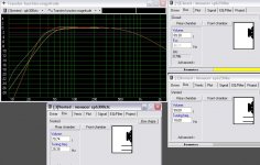
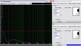
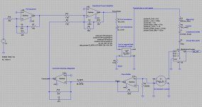
😱 Sorry for a mistake made in the picture (post #2) that occurred when I posted a a misguiding phase plot showing an all pass phase response instead of a correct flat line.
A new revised picture:
b🙂
Attachments
hi Helmuth,
what a nice loudspeaker cabinet design software you have ! I think I'll give it a try later on.
The Erik Baekgaard concept is not about extending the output in the deep bass range, nor ensuring a low group propagation delay error in the deep bass range. Actually, as you may have noticed, the woofer transfer function is considered to extend down to DC. The Baekgaard concept is about selectively highpass filtering the tweeter (more than a 1st order) and selectively lowpass filtering the woofer (more than a 1st order) and then determine the transfer function of the "filler" unit also called the "missing link". For getting a perfectly reconstructed wave when summing the three transducers outputs.
The math I've sketched above is straightforward. I can't make it simpler. Do you own a simple textbook about electronic filters ? If not, start googling, maybe ? There should be easy and intuitive tutorials on the web nowadays.
The big issue with the Baekgaard concept is to ensure that the summation is accurate in the acoustic domain. This is not a trivial task knowing that a d'Appolito arrangement is needed (WMTMW) for getting virtual coincident sources. You need the d'Appolito layout because the Baekgaard crossover (unlike a Linkwitz-Riley) generates significant inter-driver phase shifts in the overlap region. And the overlap region is wide as the order of the filter is only 2.
There are four very important tests to be carried out to check if your WMTMW arrangement is correctly dimensionned. I think this is what bjorno wanted to express in a nutshell, in his above post. Thanks.
1. If you disconnect the medium, there should be no sound coming out at the crossover frequency (here 1700 Hz). This is because the woofer and the tweeter do cancel each other at the crossover frequency. Of course you will hear some sound. You will hear the harmonic 2 and the harmonic 3, and you can do nothing for correcting this, unless paying more money for more linear drivers. Then you need to ensure that you don't hear any harmonics even at loud listening levels. Call it a job ! But it is not finished yet. If you hear some fundamental (at 1700 Hz), it means that the sensitivity of the drivers need to be adjusted (use a small serial resistor). It you still hear some fundamental (1700 Hz), it means that there is a geometric issue preventing the waves blending and mutually cancelling. You thus need to optimize the way the drivers are mounted, like time-aligning the woofers with the tweeter.
2. If you only drive the woofers, and wire them antiphase, you are supposed to hear no sound. Do the experiment. Then you discover that you can hear some sound depending on your position. If the woofers have a big diameter like 200 mm or 250 mm, their centers are more than 270 mm apart because of the space being taken by the medium and tweeter inbetween. How far do you think you need to be for the waves correctly blending, without suffering from proximity effects ? How to avoid proximity effects, allowing the two sources to blend even at a close listening distance ? You, listening just in front, and also offset like 30 degree or 60 degree ? Then you realize that you can only succeed with the Baekgaard concept, using small woofers. If you use 165 mm woofers, their centres get separated by something like 240 mm. This corresponds to a sound vavelenght of 1250 Hz. And the crossover frequency is 1700 Hz. You see the difficulty ?
3. If you only drive the medium, and wire them antiphase, you are supposed to hear no sound. Do the experiment. Then you discover that you can hear some sound depending on your position. If the medium have a diameter like 2 inches, their centers are 120 mm apart because of the space being taken by the tweeter inbetween. How far do you think you need to be for the waves correctly blending, without suffering from proximity effects ? How to avoid proximity effects, allowing the two sources to blend even at a close listening distance ? You, listening just in front, and also offset like 30 degree or 60 degree ? Then you realize that you can only succeed with the Baekgaard concept, using small medium drivers. A distance of 120 mm corresponds to a sound vavelenght of 2500 Hz. And the crossover frequency is 1700 Hz.
4. Now that from point 1, the woofers and the tweeter got time aligned, it is also mandatory to time align the medium drivers on the rest.
The points 1-2-3-4 are the real world issues of the Baekgaard concept. Many have failed implementing a proper Baekgaard, because of ignoring the 1-2-3-4 points above.
However this should not be part in a discussion about the Baekgaard crossover concept and implementation, let me now show you the way you may address the deep bass range question, if you are concerned (like me) with group delay distorsion.
I thus agree with you that once you go for a Baekgaard arrangement providing a zero phase error in the reconstructed signal, you may also want the deep bass range being preserved from excessive phase distorsion. Of course you know that all loudspeakers are high-pass systems, so what you are actually searching is a high-pass transfer function compatible with a Bass-Reflex (hence 4th order), having the lowest phase distorsion (lowest group delay) in the useable frequency range, like 50 Hz to 2700 Hz. Any textbook will tell you that what you are searching for is a 4th-order Bessel highpass alignment.
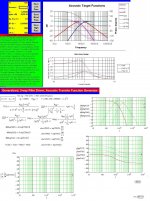
Let us take a Monacor SPH-165 CP in a Bass-Reflex arrangement.
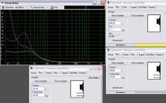
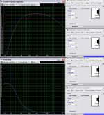
Let us first tune it to a Bessel. The box compliance needs thus to be 650µ m/N and the vent mass needs to be 34 gram.
We end up with a 43 Hz cutoff at -3 dB. The group delay is 15 ms at 30 Hz and only 7 ms at 50 Hz. This is decent. I shouldn't worry about group delay with such figures.
I confess the 43 Hz cutoff frequency may deceive.
Let us thus apply equalization for extending the bass range, with a new Bessel response as target, with a lower cutoff frequency like 31 Hz.
We end up with a 31 Hz cutoff at -3 dB. The group delay is 12 ms at 30 Hz and only 5 ms at 50 Hz. This is excellent. There are very few loudspeaker systems on earth, providing such outstanding performance.
I am now attaching the simulation files.
Regards,
Steph
what a nice loudspeaker cabinet design software you have ! I think I'll give it a try later on.
The Erik Baekgaard concept is not about extending the output in the deep bass range, nor ensuring a low group propagation delay error in the deep bass range. Actually, as you may have noticed, the woofer transfer function is considered to extend down to DC. The Baekgaard concept is about selectively highpass filtering the tweeter (more than a 1st order) and selectively lowpass filtering the woofer (more than a 1st order) and then determine the transfer function of the "filler" unit also called the "missing link". For getting a perfectly reconstructed wave when summing the three transducers outputs.
The math I've sketched above is straightforward. I can't make it simpler. Do you own a simple textbook about electronic filters ? If not, start googling, maybe ? There should be easy and intuitive tutorials on the web nowadays.
The big issue with the Baekgaard concept is to ensure that the summation is accurate in the acoustic domain. This is not a trivial task knowing that a d'Appolito arrangement is needed (WMTMW) for getting virtual coincident sources. You need the d'Appolito layout because the Baekgaard crossover (unlike a Linkwitz-Riley) generates significant inter-driver phase shifts in the overlap region. And the overlap region is wide as the order of the filter is only 2.
There are four very important tests to be carried out to check if your WMTMW arrangement is correctly dimensionned. I think this is what bjorno wanted to express in a nutshell, in his above post. Thanks.
1. If you disconnect the medium, there should be no sound coming out at the crossover frequency (here 1700 Hz). This is because the woofer and the tweeter do cancel each other at the crossover frequency. Of course you will hear some sound. You will hear the harmonic 2 and the harmonic 3, and you can do nothing for correcting this, unless paying more money for more linear drivers. Then you need to ensure that you don't hear any harmonics even at loud listening levels. Call it a job ! But it is not finished yet. If you hear some fundamental (at 1700 Hz), it means that the sensitivity of the drivers need to be adjusted (use a small serial resistor). It you still hear some fundamental (1700 Hz), it means that there is a geometric issue preventing the waves blending and mutually cancelling. You thus need to optimize the way the drivers are mounted, like time-aligning the woofers with the tweeter.
2. If you only drive the woofers, and wire them antiphase, you are supposed to hear no sound. Do the experiment. Then you discover that you can hear some sound depending on your position. If the woofers have a big diameter like 200 mm or 250 mm, their centers are more than 270 mm apart because of the space being taken by the medium and tweeter inbetween. How far do you think you need to be for the waves correctly blending, without suffering from proximity effects ? How to avoid proximity effects, allowing the two sources to blend even at a close listening distance ? You, listening just in front, and also offset like 30 degree or 60 degree ? Then you realize that you can only succeed with the Baekgaard concept, using small woofers. If you use 165 mm woofers, their centres get separated by something like 240 mm. This corresponds to a sound vavelenght of 1250 Hz. And the crossover frequency is 1700 Hz. You see the difficulty ?
3. If you only drive the medium, and wire them antiphase, you are supposed to hear no sound. Do the experiment. Then you discover that you can hear some sound depending on your position. If the medium have a diameter like 2 inches, their centers are 120 mm apart because of the space being taken by the tweeter inbetween. How far do you think you need to be for the waves correctly blending, without suffering from proximity effects ? How to avoid proximity effects, allowing the two sources to blend even at a close listening distance ? You, listening just in front, and also offset like 30 degree or 60 degree ? Then you realize that you can only succeed with the Baekgaard concept, using small medium drivers. A distance of 120 mm corresponds to a sound vavelenght of 2500 Hz. And the crossover frequency is 1700 Hz.
4. Now that from point 1, the woofers and the tweeter got time aligned, it is also mandatory to time align the medium drivers on the rest.
The points 1-2-3-4 are the real world issues of the Baekgaard concept. Many have failed implementing a proper Baekgaard, because of ignoring the 1-2-3-4 points above.
However this should not be part in a discussion about the Baekgaard crossover concept and implementation, let me now show you the way you may address the deep bass range question, if you are concerned (like me) with group delay distorsion.
I thus agree with you that once you go for a Baekgaard arrangement providing a zero phase error in the reconstructed signal, you may also want the deep bass range being preserved from excessive phase distorsion. Of course you know that all loudspeakers are high-pass systems, so what you are actually searching is a high-pass transfer function compatible with a Bass-Reflex (hence 4th order), having the lowest phase distorsion (lowest group delay) in the useable frequency range, like 50 Hz to 2700 Hz. Any textbook will tell you that what you are searching for is a 4th-order Bessel highpass alignment.
Let us take a Monacor SPH-165 CP in a Bass-Reflex arrangement.
Let us first tune it to a Bessel. The box compliance needs thus to be 650µ m/N and the vent mass needs to be 34 gram.
We end up with a 43 Hz cutoff at -3 dB. The group delay is 15 ms at 30 Hz and only 7 ms at 50 Hz. This is decent. I shouldn't worry about group delay with such figures.
I confess the 43 Hz cutoff frequency may deceive.
Let us thus apply equalization for extending the bass range, with a new Bessel response as target, with a lower cutoff frequency like 31 Hz.
We end up with a 31 Hz cutoff at -3 dB. The group delay is 12 ms at 30 Hz and only 5 ms at 50 Hz. This is excellent. There are very few loudspeaker systems on earth, providing such outstanding performance.
I am now attaching the simulation files.
Regards,
Steph
Attachments
Last edited:
winisdpro freewarehi Helmuth,
what a nice loudspeaker cabinet design software you have ! I think I'll give it a try later on.
I think of it also as a shift in time so to have the reproduction as close as possible I did try to reduce the group delay.The Erik Baekgaard concept is not about extending the output in the deep bass range, nor ensuring a low group propagation delay error in the deep bass range.
??Actually, as you may have noticed, the woofer transfer function is considered to extend down to DC.
I did understand that only the build of formula I do not see how it works.The Baekgaard concept is about selectively high-pass filtering the tweeter (more than a 1st order) and selectively lowpass filtering the woofer (more than a 1st order) and then determine the transfer function of the "filler" unit also called the "missing link". For getting a perfectly reconstructed wave when summing the three transducers outputs.
Let us take a Monacor SPH-165 CP in a Bass-Reflex arrangement.
Let us first tune it to a Bessel. The box compliance needs thus to be 650µ m/N and the vent mass needs to be 34 gram.
We end up with a 43 Hz cutoff at -3 dB. The group delay is 15 ms at 30 Hz and only 7 ms at 50 Hz. This is decent. I shouldn't worry about group delay with such figures.
I confess the 43 Hz cutoff frequency may deceive.
Let us thus apply equalization for extending the bass range, with a new Bessel response as target, with a lower cutoff frequency like 31 Hz.
We end up with a 31 Hz cutoff at -3 dB. The group delay is 12 ms at 30 Hz and only 5 ms at 50 Hz. This is excellent. There are very few loudspeaker systems on earth, providing such outstanding performance.
Sph200ke even better group delay at higher frequencies.
Stephan do you use a normal spice program to simulate the response as I see in the picture?
Attachments
Last edited:
hi Helmuth, you need to understand the context when I say that for the Baekgaard design, we have no concerns about the deep bass extension. This Baekgaard is operating at 1700 Hz. The woofer transfer function is considered as a low-pass function at 1700 Hz meaning that, yes, indeed, it is considered like extending down to DC.
You need to understand this before going deeper.
Let me be very clear, if you want to optimize the deep bass range, Baekgaard can do nothing for you. And remember : the bigger your woofer driver, the more distant they get in a d'Appolito arrangement so the more difficult the full cancellation with the tweeter at the crossover frequency (here, 1700 Hz).
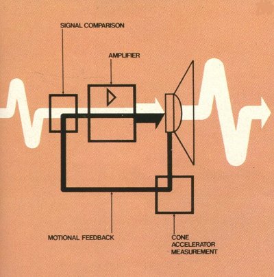
However this has nothing to do in a thread dedicated to the Baekgaard, I will now suggest Motional Feedback (as done by Philips long time ago) for extending the deep bass without any penalty regarding the group delay.
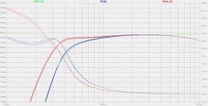
See the pictures and download the attached files for the full kit.
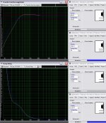
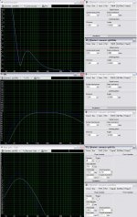
With Motional Feedback, the two Monacor SPH-165 CP can deliver a decent energy in the deep bass before facing their excursion limit. The red curve shows the result when applying the correct amount of acceleration feedback. The -3 dB cutoff is 20 Hz. The group delay at 50 Hz is 1.7 ms. You should be happy with that.
As you may have noticed, this is a moderate Motional Feedback arrangement, with less than 10 dB motional feedback. The motional feedback amount is the diference between the green curve (feedback resistor nearly infiite) and the red curve (optimal feedback resistor). A side-advantage of the motional feedback is that it reduces distorsion (if the sensor is securely glued) in the frequency band where the motional feedback is dominant. In our example, this is the 40 Hz to 300 Hz frequency band, where we can expect less than half the distorsion of a passive Closed-Box.
The simulation program I'm using is LTspiceIV, shareware in free download on the Linear Technology website.
I'm now attaching the files.
Regards,
Steph
You need to understand this before going deeper.
Let me be very clear, if you want to optimize the deep bass range, Baekgaard can do nothing for you. And remember : the bigger your woofer driver, the more distant they get in a d'Appolito arrangement so the more difficult the full cancellation with the tweeter at the crossover frequency (here, 1700 Hz).
However this has nothing to do in a thread dedicated to the Baekgaard, I will now suggest Motional Feedback (as done by Philips long time ago) for extending the deep bass without any penalty regarding the group delay.
See the pictures and download the attached files for the full kit.
With Motional Feedback, the two Monacor SPH-165 CP can deliver a decent energy in the deep bass before facing their excursion limit. The red curve shows the result when applying the correct amount of acceleration feedback. The -3 dB cutoff is 20 Hz. The group delay at 50 Hz is 1.7 ms. You should be happy with that.
As you may have noticed, this is a moderate Motional Feedback arrangement, with less than 10 dB motional feedback. The motional feedback amount is the diference between the green curve (feedback resistor nearly infiite) and the red curve (optimal feedback resistor). A side-advantage of the motional feedback is that it reduces distorsion (if the sensor is securely glued) in the frequency band where the motional feedback is dominant. In our example, this is the 40 Hz to 300 Hz frequency band, where we can expect less than half the distorsion of a passive Closed-Box.
The simulation program I'm using is LTspiceIV, shareware in free download on the Linear Technology website.
I'm now attaching the files.
Regards,
Steph
Attachments

Last edited:
That MFB simulation is very exiting. For people how do not know this it is a 35 year old design of philips active loudspeakers.The simulation program I'm using is LTspiceIV, shareware in free download on the Linear Technology website.
Regards,
Steph
http://cyrille.pinton.free.fr/electroac/lectures_utiles/asservissement/acceleration/SubServoAccelPhilipsMFB/pagemfb.html
A cut open philips flat cone MFB woofer.
An externally hosted image should be here but it was not working when we last tested it.
LTspice looks a lot like Simetrix, a freeware spice program I some times use. Although I have problems using it at work a colleague helps me starting.
I work at a engineering department and I do a lot practical tests. I am not a engineer. And one can say a math dummy 😕.
I would like to but I reaching the limit of my capabilities I guess.
Last edited:
Dutch artikel DIY MFB. The pictures and schematics are universal for everybody to read.
http://www.mfbfreaks.com/theorie/elektuur1986mfb.pdf
http://www.mfbfreaks.com/theorie/elektuur1986mfb.pdf
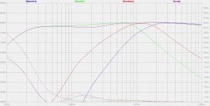
hello Helmuth,
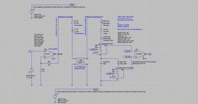
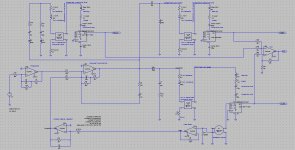
here is a quick and dirty way to get the Baeckgaard done using Motional Feedback and passive filtering. The final curve looks excellent. The group delay is essentially zero in the overlap region. Actually, the crossover is 1200 Hz instead of 1700 Hz with the values on the schematic. I needed to cheat with the sensitivities of the Tang-Band drivers. Their membrane diameters are inaccurate (inflated values) on my schematic. I needed to cheat because the Monacor SPH-165 CP delivers more dB per volt than the tiny Tang-Band medium driver and the tiny Tang-Band tweeter driver. This may be solved in the real world by connecting the two Monacor SPH-165 CP in series. This way the Tang-Band tweeter will deliver sligtly more dB per volt than the two Monacor SPH-165 in series, in such a way that the overall treble balance can be balanced using a small resistor in series with the Tang-Band tweeter. Regarding the medium drivers, I don't know if it will be possible to connect them in series, or if we will need to put them in parallel. A small resistor inserted in series with the two medium drivers will enable adjusting the "filler" level. I'll refine all this later on, updating the schematic with a better represention of the parallel and the series connexions of the drivers in general.
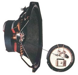
Motional Feedback demands adding an acceleration sensor under the dust cap of the woofer, exactly as described by Elektor. Thanks for providing this very valuable practical info !
Having two woofers needing to deliver the exact same amplitude and phase in the 850 to 3400 Hz range, it may be needed to equip both woofers with one acceleration sensor, and electronically mix their outputs. ON top of this, selectable resistors and capacitors may be be needed for matching the woofers bode plots.
This is going to be precision work ! This is where the DIY concept is at best. In a commercial environment, only very few people can afford buying loudspeaker systems embedding all those complications, all those high precision manipulations.
In this schematic, the lowpass filtering of the woofer is not compliant with the Baekgaard theory. With this schematic, it looks more 1st order than 2nd order. I don't know if I will be able to improve the slope without impacting the linearity of the resulting amplitude curve.
See the pictures.
I'm also attaching the whole kit in a .zip
Steph
here is a quick and dirty way to get the Baeckgaard done using Motional Feedback and passive filtering. The final curve looks excellent. The group delay is essentially zero in the overlap region. Actually, the crossover is 1200 Hz instead of 1700 Hz with the values on the schematic. I needed to cheat with the sensitivities of the Tang-Band drivers. Their membrane diameters are inaccurate (inflated values) on my schematic. I needed to cheat because the Monacor SPH-165 CP delivers more dB per volt than the tiny Tang-Band medium driver and the tiny Tang-Band tweeter driver. This may be solved in the real world by connecting the two Monacor SPH-165 CP in series. This way the Tang-Band tweeter will deliver sligtly more dB per volt than the two Monacor SPH-165 in series, in such a way that the overall treble balance can be balanced using a small resistor in series with the Tang-Band tweeter. Regarding the medium drivers, I don't know if it will be possible to connect them in series, or if we will need to put them in parallel. A small resistor inserted in series with the two medium drivers will enable adjusting the "filler" level. I'll refine all this later on, updating the schematic with a better represention of the parallel and the series connexions of the drivers in general.
Motional Feedback demands adding an acceleration sensor under the dust cap of the woofer, exactly as described by Elektor. Thanks for providing this very valuable practical info !
Having two woofers needing to deliver the exact same amplitude and phase in the 850 to 3400 Hz range, it may be needed to equip both woofers with one acceleration sensor, and electronically mix their outputs. ON top of this, selectable resistors and capacitors may be be needed for matching the woofers bode plots.
This is going to be precision work ! This is where the DIY concept is at best. In a commercial environment, only very few people can afford buying loudspeaker systems embedding all those complications, all those high precision manipulations.
In this schematic, the lowpass filtering of the woofer is not compliant with the Baekgaard theory. With this schematic, it looks more 1st order than 2nd order. I don't know if I will be able to improve the slope without impacting the linearity of the resulting amplitude curve.
See the pictures.
I'm also attaching the whole kit in a .zip
Steph
Attachments
Last edited:
yes indeed. You can go to AES E-Library
Type "Loudspeakers-The Missing Link" in the search box and click on the search button.
The AES library search engine will list the Erik Baekgaard papers.
Type "Loudspeakers-The Missing Link" in the search box and click on the search button.
The AES library search engine will list the Erik Baekgaard papers.
DIY motional feedback kit Elektuur 1986.
http://www.keepandshare.com/doc12/572/elektuur1986mfb-pdf-1-0-meg?da=y
http://www.keepandshare.com/doc12/572/elektuur1986mfb-pdf-1-0-meg?da=y
Steph, was any speaker based on the design directions outlined in your post #3 completed? (without the MFB.) I suspect that your results could be quite good (if the listener understands and respects the limitations).
- Status
- Not open for further replies.
- Home
- Loudspeakers
- Multi-Way
- WMTMW Baekgaard