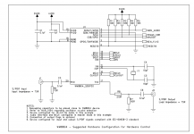
Hi, I'm busy building a I2S to S/PDIF circuit using the WM8804 in hardware mode. I have a question about the "setting" pins, like:
SDIN (0=HW mode, 1=SW mode)
SCLK (0=slave mode, 1=master mode)
SDOUT (setting data format)
GPO0 (setting data format)
CSB (setting S/PDIF)
I'm a real noob so this leads to my question:
Why do some of these pins need 10k resistors (like CSB) and some not (SIDN)? Can they be omitted? 🙂
SDIN (0=HW mode, 1=SW mode)
SCLK (0=slave mode, 1=master mode)
SDOUT (setting data format)
GPO0 (setting data format)
CSB (setting S/PDIF)
I'm a real noob so this leads to my question:
Why do some of these pins need 10k resistors (like CSB) and some not (SIDN)? Can they be omitted? 🙂
Attachments
Yes I did that, I'm dreaming about that datasheet (really). Problem is I can't figure it out from there...
If the signals are used then yes you need 10k on the outputs.
They look like open collector output signals.
They look like open collector output signals.
I don't like leaving open drain outputs dangling. I'd tie them to VCC with resistors as shown. It's one $0.10 resistor network... You'll need most of the signals (UNLOCK, NON-AUDIO, and TRANS_ERR for sure) for your DAC anyway.
Tom
Tom
It's because some pins funtion only as inputs or outputs, while other pins function in dual mode. These dual mode pins are used for chip option programming when in hardware mode. They are read just after chip reset, and then function as outputs thereafter. Which means that they should not be directly tied to power or ground for chip programming. Each dual mode pin should instead be connected through a 10K resistance so they are not shorted to power or ground after they switch to function as outputs.
Last edited:
So called pull-up or pull-down resistors to make it either a 1 or 0 level logically without being a short when the chip changes pins from inputs to outputs.....
Excellent explanation by Ken Newton !
Excellent explanation by Ken Newton !
Last edited:
Hi jean-paul, thanks 🙂
But... why is SDIN tied directly (without resistor) to ground in some designs? Because it's an input only? Take this example:
http://www.dddac.com/dddac1794_spdif.html
CSB has the pull-down resistor, but SDIN does not. Why is that?
But... why is SDIN tied directly (without resistor) to ground in some designs? Because it's an input only? Take this example:
http://www.dddac.com/dddac1794_spdif.html
CSB has the pull-down resistor, but SDIN does not. Why is that?
Last edited:
Hi jean-paul, thanks 🙂
But... why is SDIN tied directly (without resistor) to ground in some designs? Because it's an input only? Take this example:
DDDAC 1794 NOS DAC - Non Oversampling DAC with PCM1794 - no digital filter - modular design DIY DAC for high resolution audio 192/24 192kHz 24bit
CSB has the pull-down resistor, but SDIN does not. Why is that?
Yes, because SDIN is an input pin only. It does not switch to function as an output.
Yes, because SDIN is an input pin only. It does not switch to function as an output.
Ok!!
- Status
- Not open for further replies.
- Home
- Source & Line
- Digital Source
- WM8804 settings: resistors needed or not?