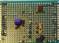
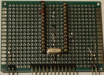
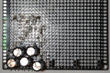
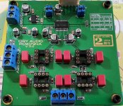
More PCM1794.
Managed to add a few more parts to the board today.
I have since the pics were taken isolated the os-con on the bottom with tape.
Doubled up on the caps compared to schematic, except for the tantalums that I only had 5pcs. So where they are parallelled, there's 44uF and the schematic says 47uF. I will however have more capacitance off-board.
Attachments
Any chance a moderator can change the title of this thread to Mayday modular DAC project or similar since it's no longer only about WM8740 in different configurations?
Thank you 🙂
EDIT:
Does anyone know of a good schematic using 4x TDA1387? I ordered 5pcs a while ago and I figured I might as well run something like parallel+balanced using 4x TDA1387's.
I/V, I prefer to go the active, discrete route on that.
Thank you 🙂
EDIT:
Does anyone know of a good schematic using 4x TDA1387? I ordered 5pcs a while ago and I figured I might as well run something like parallel+balanced using 4x TDA1387's.
I/V, I prefer to go the active, discrete route on that.
Last edited:
Only thing I got done today was some work on the enclosure for the modular DAC.
One 0-9VAC 1200mA EI for +5Vdc and +3.3Vdc supplies.
One 12-0-12 500mA EI for +/-12Vdc supply.
I'll probably drop the rectified voltage from the 0-9VAC transformer to 8-9Vdc then follow that by super regulators, probably two per rail(2x +5Vdc & 2x +3.3Vdc).
This way each board (SPDIF to I²S, D/A) gets it's own regulator. The AD1896A board will have to share regulator with one of the other boards until I decide if I'll keep it in the DAC or not.
I haven't decided on regulation for the 12-0-12VAC transformer yet(will supply filter/buffer boards).
Attachments
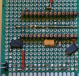
Worked a bit on the "motherboard" and on the WM8805 boards today.
WM8805 with 12Mhz oscillator connected like this
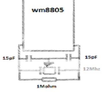
33R 1% 1206 SMD resistors on the I2S output pins.
All wiring done with 0.33mm 99.99% silver wire...mainly because it's very soft and easy to use.
Waiting for the PCB switches to arrive before I can populate much more.


220uF/10V polymer capacitors where the power supplies connects to the board.

The "motherboard" to which I'll connect the modules, voltage regutators etc
220uF/10V Rubycon ZA one per rail (2x +5Vdc and 2x +3.3Vdc) with a nice 100nF SMD on the bottomside of the board.
Wiring is same as above, silver wire.


Attachments
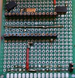
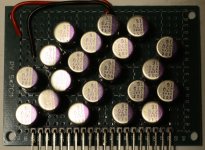
Got some more work done on the low voltage rails cap bank.
Some wiring left to do.
4x 270uF/16V Sanyo SEPC per rail (3x +5V rails and 2x +3.3V rails)
The +/-12Vdc cap bank is done, looks messy but measures ok.
4x Rubycon ZL 470uF per rail.
Some wiring left to do.
4x 270uF/16V Sanyo SEPC per rail (3x +5V rails and 2x +3.3V rails)
The +/-12Vdc cap bank is done, looks messy but measures ok.
4x Rubycon ZL 470uF per rail.
Attachments
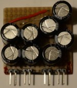
Spent some time today measuring transistors, but I did get some work done on the "motherboard" for the DAC.
Added one more +5V rail for a total of 3.
So now rails are: +3.3V x2, +5V x3
Rubycon ZA 220uF x1 per rail on the motherboard, where connections from voltage regulators will be.
OS-CON SEPC 270uF x4 per rail on the +3.3V & +5V cap bank board.
Plus of course some capacitance on the power supply inputs of each board (module). Might be wrong, but it feels like splitting the capacitance to several "small islands" is better than having a big chunk on one place with long wires/tracks to or from voltage regulators and each load.
With the LCR-tester/transistor-tester I recently got, the ZA's have an ESR of 0.06ohms and the SEPC 0.05ohms.
(Btw, I was amazed to see the difference between Vishay MKP 100nF and some MKT 100nF that I don't remember the brand of right now...the Vishay's were nearly 3 times lower in ESR).
Attachments
Project is not dead...just waiting for a whole bunch of parts.
I've got 3000pcs 1% 0805 SMD resistors on the way as well as 570pcs NP0 & X7R 0805 capacitors in addition to the 500pcs I got last week.
Figured I might as well get all the SMD caps/resistors I'll need/will need soon enough in one go. Works out alot cheaper that way.
The project is more or less halted due to some other parts though.
PCB switches, 12pin and 20pin female headers.
Good thing I have two headamp projects going too, keeping me busy.
One Hiraga "clone", the term clone is used losely in this case.
And an improved version of the BCL clone that I've enjoyed for some years(the regular BCL clone that is).
On monday I'll get the resistors needed to get going again.
Hopefully the PCB switches will arrive as well.
Hopefully the PCB switches will arrive as well.
Got the resistors and one of the two types of switches I need. Didn't get the 4pin 2-switch on-off ones.
Been occupied with a few headamp projects as I got a pair of Fidelio X2's as an early x-mas present from my fiance.
Got some super regulator PCB's as well, so the DAC will have nice, clean power 🙂
Been occupied with a few headamp projects as I got a pair of Fidelio X2's as an early x-mas present from my fiance.
Got some super regulator PCB's as well, so the DAC will have nice, clean power 🙂
As I am nearing "done-status" on the headamp I've been working on lately, my attention will be re-focused to this DAC project.
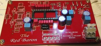
I've expanded it a bit more by buying a Red Baron TDA1541A board today.
Now I need to decide if I'll go NOS or not.
If I go OS, I'll have to figure out the best way to get oversampling without the SAA7220P/B (don't like that IC at all).
I'll power all modules of the DAC with super regulators in an effort to give it the best chance of performing well.
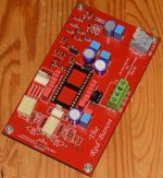
Recieved the Red Baron board last week, a very nice looking PCB 🙂
Just started to populate it with some bits I had at home.

I've got more parts at home, but none I think of as good enough.
Since I'll be using one of my TDA1541A IC's I want to make the most of it, and so I ordered very nice capacitors and resistors, and the 2pcs 2SK216 should I decide to use the onboard I/V and output.
So..
Now I have two different I-out DAC IC's, PCM1794 and TDA1541A.
I've got one WM8740 and another one that is on the way.
I wish I could afford getting a 100% genuine PCM1704 to try as well.
SPDIF to I2S I have the following options
DIR9001 two versions
WM8805
WM8804 (ordered a board, so that I have something to fall back on should my perf boarded ones not work)
I'm still not sure if I'll try to implement the AD1896A ASRC or not.
I have a few diffferent outputs/filters, both discrete and with opamp.
Now to add to that list, I've got two versions of ECC86 outputs that I can build. One is a design I already use in my TDA1541A based DAC in my main system, the other is Mr. Borberly's design, I think he called it opamp 4 or something to that affect. It's ECC86, 2SA872, 2SK216, 2SJ79.
I've got all parts needed for the Borberly design on the way, except the ECC86 that I have already.
As for I/V, I have not yet landed on any design. There are alot of them out there and the only one except opamps that I have personal experience with is a passive I/V followed by a tube stage.
I'd prefer an I/V that doesn't require very high voltages, I've got a 24-0-24VAC transformer on the way for the ECC86, but other than that I hope to power the DAC with 0-9VAC 1500mA, 12-0-12VAC 500mA and the ordered 24-0-24VAC 30W.
I don't think I can fit more transformers in the enclosure considering I'll be using a few super regulators as well.
Since my solder station died and the new one won't arrive for a couple of days, I'm back at looking through what's been done, what can be done better and what still needs to be done.
In a way it was perfect timing for the solder station to give up 😉
I did get some more parts on to the Red Baron board before it died though.
In a way it was perfect timing for the solder station to give up 😉
I did get some more parts on to the Red Baron board before it died though.
Attachments
This project is both growing and slowly moving forwards...
Sorry about picture quality, I didn't use the Nikon D5200 but my phone camera as I've been too lazy.
I got a WM8804 module off ebay should my WM8805 not work as expected.
I've got to say, my TSSOP28 soldering doesn't look to bad (WM8740's, not the WM8804 board)

I started a dual WM8740 board.
Digital and analog grounds are separate, but connected via a ferrite bead bypassed by a 100nF Wima.
I2S input will be via two 74HC74 flip-flops. I'm waiting for those as well as alot of other parts.


Started a new WM8805 board that will use larger, better parts rather than small SMD's.
I haven't gotten started on the +3.3Vdc supplies or mode switches as I'm waiting for a few parts.


The boards are 8*12cm dual side plated through perf boards.
I'll try to use as small a footprint I can on all parts of the DAC as the power supply will take up alot of space. The enclouse is rather high though I will try and take as much advantage of that as possible.

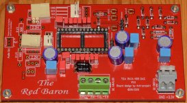
The Red Baron board, not much more done here. Pretty much done except for connectors and whatever I/V I finally decide on using.


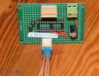
Between the WM8804/05 I'll use an NPC SM5814. Thanks to my good friend Dave (Torchwood something here) for booth the IC and the schematic.
The board is still being built, I need some more connectors to finish it.
I have used some parts not in the schematic I was given by Dave, so if they are dumb additions, it's on me.
The added parts are the ferrite beads on the +Vdc and GND, the Rubycon ZA 220uF bypassed by a 100nF Wima.
I will not post the schematic here, that will be up to Dave to do should he want to do so.


And finally I have another discrete output under construction/collecting parts-fase.
I'll test using Borberly's Op amp 4, I think it's called, as output.
Using two Philips ECC86 followed by two pairs 2SK216/2SJ79.
Managed to get genuine pairs of the mosfet's off ebay (tested with transistor tester).
I've bought an EI 2x24VAC 30VA transformer. I don't know if that will be enough for the Borberly circuit though.
The heaters I was thinking about using a separate 220V 6VAC transformer.
The mains voltage here is 230V, but I've used 220V stuff before without problems.
Should the 6VAC small EI transformers secondaries put out a voltage not suited for the heaters, I'll use it with bridge rectifier and voltage regulator and use 6.3Vdc for the heaters.
I've only just gotten started on this output
The tubes will be mounted on two 4*6cm perf boards that attach to a 8*12cm perf board with the transistors etc via 90 degree angled pin headers for vertical mounting of the tubes.


Wow, this turned out to be a long post...
Anyway, now I think the thread is up to speed with the actual build 🙂
Sorry about picture quality, I didn't use the Nikon D5200 but my phone camera as I've been too lazy.
I got a WM8804 module off ebay should my WM8805 not work as expected.
I've got to say, my TSSOP28 soldering doesn't look to bad (WM8740's, not the WM8804 board)

I started a dual WM8740 board.
Digital and analog grounds are separate, but connected via a ferrite bead bypassed by a 100nF Wima.
I2S input will be via two 74HC74 flip-flops. I'm waiting for those as well as alot of other parts.


Started a new WM8805 board that will use larger, better parts rather than small SMD's.
I haven't gotten started on the +3.3Vdc supplies or mode switches as I'm waiting for a few parts.


The boards are 8*12cm dual side plated through perf boards.
I'll try to use as small a footprint I can on all parts of the DAC as the power supply will take up alot of space. The enclouse is rather high though I will try and take as much advantage of that as possible.

The Red Baron board, not much more done here. Pretty much done except for connectors and whatever I/V I finally decide on using.


Between the WM8804/05 I'll use an NPC SM5814. Thanks to my good friend Dave (Torchwood something here) for booth the IC and the schematic.
The board is still being built, I need some more connectors to finish it.
I have used some parts not in the schematic I was given by Dave, so if they are dumb additions, it's on me.
The added parts are the ferrite beads on the +Vdc and GND, the Rubycon ZA 220uF bypassed by a 100nF Wima.
I will not post the schematic here, that will be up to Dave to do should he want to do so.


And finally I have another discrete output under construction/collecting parts-fase.
I'll test using Borberly's Op amp 4, I think it's called, as output.
Using two Philips ECC86 followed by two pairs 2SK216/2SJ79.
Managed to get genuine pairs of the mosfet's off ebay (tested with transistor tester).
I've bought an EI 2x24VAC 30VA transformer. I don't know if that will be enough for the Borberly circuit though.
The heaters I was thinking about using a separate 220V 6VAC transformer.
The mains voltage here is 230V, but I've used 220V stuff before without problems.
Should the 6VAC small EI transformers secondaries put out a voltage not suited for the heaters, I'll use it with bridge rectifier and voltage regulator and use 6.3Vdc for the heaters.
I've only just gotten started on this output
The tubes will be mounted on two 4*6cm perf boards that attach to a 8*12cm perf board with the transistors etc via 90 degree angled pin headers for vertical mounting of the tubes.


Wow, this turned out to be a long post...
Anyway, now I think the thread is up to speed with the actual build 🙂
Got started on the 74HC74 input for the dual WM8740 board.
When it's done, I'll solder it on to the WM8740 board like this
An externally hosted image should be here but it was not working when we last tested it.
When it's done, I'll solder it on to the WM8740 board like this
An externally hosted image should be here but it was not working when we last tested it.
I forgot, I have a fallback plan for the PCM1794 as well, should my perf boarded ones not work.
I have started one of these boards, and another is on the way(for both dual and mono)
I have all parts except the SMD lytic caps, but I'm waiting to populate more until those arrive. This so that I have more space when soldering them.
I don't have a hot air station, just a fine tip on my Weller WHS40D.
I didn't have any SMD ferrite beads, hence the axial one. Will that compromise performance?


A little bit more done today.
SM5814 board is done.
May have gone overboard on the ferrite beads, but I've got plenty.
Red Baron board is done (unless I decide to fully populate it at some point(I have the parts needed).
I went with Mil.spec RG178 coaxial cable(very small diameter and quite managable for a coaxial cable) for digital signal transfer, tying shields together at on end and connecting them to GND.
I got the second tube needed for the Borberly output (op amp 4)
I bought a used tube, but one that tested very strong:
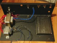
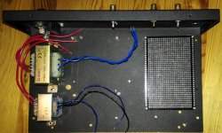
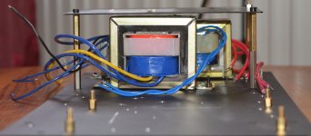
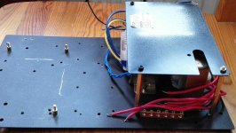
I also got some more work done on the enclosure.
Space was getting tight, so I added a "second floor" above the power transformers.
Had I finished and tested the vregs, I could in theory have tested one setup today(also would have needed to do some more wiring...and an I/V-stage..almost forgot about that).


Hopefully I'll get some work done on the WM8805 board and the dual WM8740 board tomorrow.
SM5814 board is done.
May have gone overboard on the ferrite beads, but I've got plenty.
Red Baron board is done (unless I decide to fully populate it at some point(I have the parts needed).
I went with Mil.spec RG178 coaxial cable(very small diameter and quite managable for a coaxial cable) for digital signal transfer, tying shields together at on end and connecting them to GND.
I got the second tube needed for the Borberly output (op amp 4)
I bought a used tube, but one that tested very strong:
TESTED ON HICKOK TV-7A/U TUBE TESTER
MINIMUM GOOD VALUE: 32/32
MEASURED VALUE: 74/70 ( > 131% )
I also got some more work done on the enclosure.
Space was getting tight, so I added a "second floor" above the power transformers.
Had I finished and tested the vregs, I could in theory have tested one setup today(also would have needed to do some more wiring...and an I/V-stage..almost forgot about that).


Hopefully I'll get some work done on the WM8805 board and the dual WM8740 board tomorrow.
Attachments
Small update.
I've recieved some more parts and populated the first of two PCM1794 PCB's a bit more.
Sorry about the picture quality, too lazy to get out the DSLR again.


Swapped the improvised axial ferrite bead for a 1206 0.15R 300mA SMD

For the Red Baron, I'm waiting for I/V resistors and caps plus better quality resistors for the Borbely opamp 4 that I'll try directly after the passive I/V.
I've also signed up for another board to try parallel TDA1541A's.
I'm working on the dual WM8740 board with two 74HC74 on the I2S input.
For now it looks like a rats nest, even more than usual 😀
WM8805 board, I'm waiting for a 12Mhz 0.1ppm TCXO and some other parts.
That's just about it for now on the modular dac project.
I will have several output options, opamp, discrete transistor, tubes, signal transformers(Edcor XSM, Thanks Dave!). Thanks to Abraxalito for his help as well, it's been invaluable.
I'll also have options for both passive and active I/V, the option to add an ASRC, three different digital receiver IC's.
Now there's just getting all boards done so that I may enjoy the work put in these last months as well...
The fist PCM1794 board is done.
Second board(for running one PCM1794/channel) is on it's way along with a few missing parts to complete that as well.
Might try it with the on board I/V and output first, then take the signal from the dip8 sockets and try other I/V and output stages.
I haven't looked at the board to determine if/what components would need to be removed when going with off board I/V etc.
I'm thinking maybe passive I/V and a buffer stage followed by a pair of edcor XSM signal transformers, or go opamp I/V and discrete buffer.
I'm still waiting for a few parts to arrive before I can continue on the WM8805 board and the dual WM8740 board.
Attachments
- Status
- Not open for further replies.
- Home
- Source & Line
- Digital Line Level
- Wm8740, possible discrete filter/buffer?